Recommendations on the External Pull-up Resistor for the ace / ace 2 GPIO Output Circuit#
The GPIO output circuit sample diagram includes a resistor.
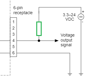
A typical application for this could be to trigger the switching input of a lighting using the GPIO line 2 of a Basler ace 2 camera. 24 VDC are to be switched on or off (no loads are switched, there is an extra switching input in the lighting). The wiring example suggested by Basler is exactly intended for such an application:

An additional external resistor (marked green) must be added to protect the internal wiring.
There is no official pull-up resistor recommendation from Basler for ace or ace 2 cameras.
An exact specification of this external pull-up resistor is not meaningful, as it strongly depends on the connected device.
The technical specification of the cameras ("Electrical Requirements - General Purpose I/O Lines - Operation as Output") should be used to calculate the correct resistor value. The actual value mainly depends on the level of the external I/O voltage at the external pull-up resistor.
It is important to observe the maximum permissible load current, which is given in the specifications as 50mA.
In the function as logic level, a resistance value of 2 k Ω should be sufficient in many cases.
Provided that the maximum I/O voltage is <30 VDC, however, a minimum value of 600 Ω must always be provided for the external pull-up resistor.