Computing 3D data
While on stereo pipelines, such as rc_visard and stereo_ace, disparity images are computed by matching
the left and right camera images, on blaze pipelines the 3D data is internally converted into
a disparity image that can be used to compute depth information using a provided virtual baseline.
The following sections describe how disparity, error and confidence images can be used to compute depth data and depth errors.
Computing depth images and point clouds
The following equations show how to compute an object point’s actual 3D coordinates  in the
camera coordinate frame
from the disparity image’s pixel coordinates
in the
camera coordinate frame
from the disparity image’s pixel coordinates  and the disparity value
  in pixels:
(1)
where  is the focal length after rectification in pixels and
  is the stereo baseline in meters, which was determined during calibration. These values
are also transferred over the GenICam interface (see
Custom GenICam features of the rc_cube).
is the stereo baseline in meters, which was determined during calibration. These values
are also transferred over the GenICam interface (see
Custom GenICam features of the rc_cube).
Note
The rc_cube reports a focal length factor via its various
interfaces. It relates to the image width
for supporting different image resolutions. The focal length
in pixels can be easily obtained by multiplying the focal length factor
by the image width in pixels.
Please note that the equations assume that the coordinate
frame is centered in the principal point that is typically in the center of the image,
and refer to the middle of the pixel, i.e. by adding 0.5 to the
integer pixel coordinates. The following figure shows the definition of the image coordinate
frame.
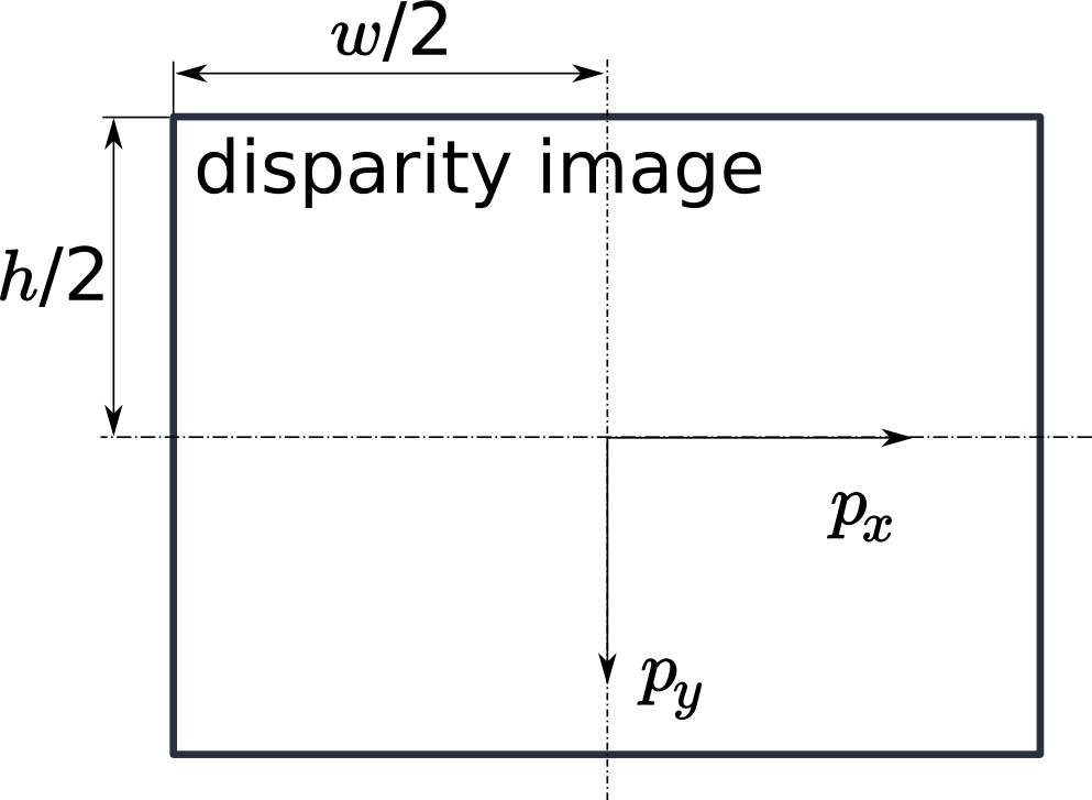
Fig. 11 The image coordinate frame’s origin is defined to be at the image center
–  is the image width and
  is the image height.
The same equations, but with the corresponding GenICam parameters are given in Image stream conversions.
The set of all object points computed from the disparity image gives the point
cloud, which can be used for 3D modeling applications. The disparity image is
converted into a depth image by replacing
the disparity value in each pixel with the value of  .
.
Confidence and error images
For each disparity image, additionally an error image and a confidence image are provided,
which give uncertainty measures for each disparity value. These images
have the same resolution and the same frame rate as the disparity image. The
error image contains the disparity error  in pixels corresponding
to the disparity value at the same image coordinates in the disparity image.
The confidence image contains the corresponding confidence value
in pixels corresponding
to the disparity value at the same image coordinates in the disparity image.
The confidence image contains the corresponding confidence value  between 0 and 1. The confidence is defined as the probability of the true
disparity value being within the interval of three times the error around the
measured disparity , i.e.,
between 0 and 1. The confidence is defined as the probability of the true
disparity value being within the interval of three times the error around the
measured disparity , i.e., ![[d-3d_{eps}, d+3d_{eps}]](_images/math/e3b385693497bff6357b3cec18df0db1316b8b4a.svg) .
Thus, the disparity image with error and confidence values can be used in
applications requiring probabilistic inference. The confidence and error values
corresponding to an invalid disparity measurement will be 0.
.
Thus, the disparity image with error and confidence values can be used in
applications requiring probabilistic inference. The confidence and error values
corresponding to an invalid disparity measurement will be 0.
The disparity error (in pixels) can be converted to a depth error  (in meters) using the focal length (in pixels), the baseline (in meters), and the disparity
value (in pixels) of the same pixel in the disparity image:
(in meters) using the focal length (in pixels), the baseline (in meters), and the disparity
value (in pixels) of the same pixel in the disparity image:
(2)
Combining these equations allows the depth error to be related to the depth:
