daA4200-30mci-JNANO-NVDK#
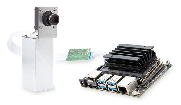
The kit contains a 13 MP dart camera module, a processing board based on the NVIDIA Jetson Nano SoM, and accessories. With these components, you can build a test environment in which you can evaluate the camera module and plan how to integrate it into your embedded vision system.
Kit Contents#
The kit contains the following components:
- Basler dart daA4200-30mci camera module, S-mount
- Evetar lens M13B0618W F1.8 f6mm 1/3"
- Jetson Nano Developer Kit processing board
- Basler BCON for MIPI to JNANO adapter board
- microSD card with preinstalled system software
- Flexible flat cable, 0.2 m
- Flexible flat cable, 0.05 m
- USB 2.0 cable: A / Micro B, 1.8 m
- HDMI 2.0 cable: A / A, 1.5 m
- GigE cable: Cat 5e, 2.0 m
- Power supply: 5 V @ 4 A, AC adapter
- Mounting kit (includes camera mounting plate, spacer bolts, screws, and nuts)
- Monopod
Hardware Installation#
To install and connect the components provided in this kit:
- Attach four spacer bolts to the bottom of the mounting plate using four screws (M2x4) included in the mounting kit.
- Attach the camera to the mounting plate using four screws (M2x12) with the lens sticking through the hole of the plate. Fix the screws with the nuts.
- Remove the protective caps from the lens and mount the lens on the camera. Be careful not to damage any camera components by inserting the lens too deep.
- Lead the flexible flat cable through the rectangular cutout of the mounting plate.
-
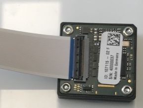
Connect the 0.2 m FFC cable to the camera. To do so:
- Open the black locking bar on the FFC connector.
- Push the end of the cable firmly into the FFC connector with the blue color facing away from the camera. See image below.
- Re-lock the connector by pushing the locking bar back into its original position.
-
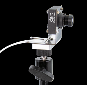
Mount the mounting plate on the monopod. See image below.
-
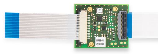
Connect the other end of the 0.2 m FFC cable to the connector on the adapter board. Make sure that the blue part of the cable faces away from the adapter board (see image below, right side).
-
Connect the 0.05 m FFC cable to the other connector on the adapter board. To do so:
- Open the black locking bar on the adapter board by pulling it away from the board.
- Push the end of the cable firmly into the FFC connector with the blue color facing away from the adapter board (see image below, left side).
- Re-lock the connector by pushing the locking bar back into its original position.
-
Connect the other end of the 0.05 m FFC cable to one of the two CSI connectors on the Jetson Nano board. To do so:
- Unlock the connector on the board by pulling the upper part towards you. Be careful not to apply too much pressure, as the connector lock might break.
- Insert the cable vertically into the connector. Make sure that the blue part of the cable end faces away from the board. See image below.
- Re-lock the connector by pushing the locking bar back into its original position.
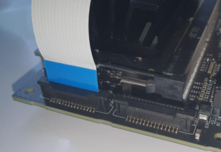
-
Insert the microSD card delivered with the kit into the microSD card slot on the Jetson Nano board.
Acquiring Your First Images#
To acquire your first images using the pylon Viewer:
- Make sure that the following items are available:
- Monitor with an HDMI port
- USB mouse
- USB keyboard
- Connect the HDMI cable delivered with the kit to the HDMI connector on the processing board and to the monitor. Turn the monitor on.
- Connect a mouse and a keyboard to any of the USB ports on the processing board.
- Connect the power supply delivered with the kit to the barrel jack connector of the processing board. Make sure that the J48 pins next to the barrel jack connector are connected by a jumper. This is necessary to power the board through the barrel jack.
- Connect the power supply to the mains socket.
The board boots up. - During the initial boot phase, you will be guided through a start-up procedure where you must accept the kit's license agreement, select your language and keyboard settings, and generate a user account.
-
After the start-up procedure, click the green Ubuntu icon in the top left and type
pylon: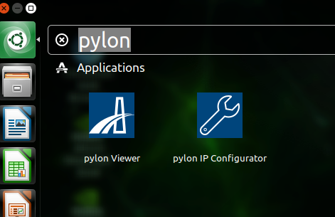
-
Click the pylon Viewer icon.
The pylon Viewer application lets you configure the camera, acquire and save images, and more. - In the pylon Viewer, open the daA4200-30mci camera device.
- Configure the image ROI by setting the
Width,Height,OffsetX, andOffsetYparameters.
Due to a known issue, the camera currently only supports values for theWidthparameter that are multiples of 32 and for theHeightparameter that are multiples of 16. For example, to get the maximum resolution, change theWidthparameter to 4192 and theHeightparameter to 3120. - Click the Continuous Shot icon to start image acquisition.
For more information about the Basler pylon Software Suite and on how to develop your vision applications using the SDK, visit the Basler pylon website.
For more information about the hardware installation and getting started, also refer to NVIDIA's Getting Started Page for the Jetson Nano.
External Triggering#
To trigger image acquisition by external trigger signals, proceed as follows:
-
Connect the external trigger source to the adapter board via the pin header highlighted in the image below.
Observe the circuit diagram shown below the image of the adapter board.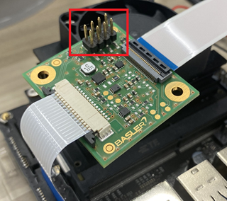
-
Apply the external trigger signal to pin 2 (GPIx).
Info
The trigger voltage should not exceed 1.8 V. Voltages above 1.8 V may permanently damage the device.
-
To configure the camera for external triggering, set the
TriggerModeparameter toOn.
Debian Packages#
This Basler Embedded Vision Development Kit comes with a pre-installed Linux operating system. It includes the following Debian packages provided by Basler:
| File name | Contents |
|---|---|
| pylon_6.1.1.19861-RC3-deb0_arm64.deb | pylon API and pylon Viewer application used to access and configure the camera |
| basler-dart-bcon-mipi-gentl-producer_1.3.0_arm64.deb | Basler dart E GenTL producer used to provide streaming support with Basler BCON for MIPI cameras in pylon |
| nvidia-l4t-kernel_4.9.140-tegra-32.4.2-20200408182157_arm64.deb | NVIDIA L4T kernel including Basler camera driver |
| nvidia-l4t-bootloader_32.4.2-20200408182157_arm64.deb | NVIDIA L4T bootloader and a modified device tree enabling Basler camera support |
| nvidia-l4t-kernel-headers_4.9.140-tegra-32.4.2-20200408182157_arm64.deb | NVIDIA L4T kernel headers for development |
| nvidia-l4t-kernel-dtbs_4.9.140-tegra-32.4.2-20200408182157_arm64.deb | NVIDIA L4T kernel DTBS (Device Tree Binaries) for development |
Info
- The system image and the Debian packages provided only work with the Jetson Nano Developer Kit, revision B01, which has two CSI ports. It doesn't work with the older, discontinued version, which only has one CSI port.
-
If you already have a system running and want to install the Debian packages provided by Basler only, you must execute the following two commands after package installation:
sudo apt-mark hold nvidia-l4t-kernel*sudo apt-mark hold nvidia-l4t-bootloader
This ensures that a system upgrade does not overwrite the kernel and bootloader packages, which would remove Basler camera support. If this happens accidentally, you must re-install the Basler Debian packages.