Application Note: Designing Signal Processing Applets for Programmable Frame Grabbers#
GPI/GPO Operators in VisualApplets#
Using VisualApplets, you can design your own, application-specific trigger system. You can, e.g., determine which signal is sent or received by which individual physical input/output pin.
In VisualApplets, you have two operators available to wire up an individual pin with your applet design:
Operator GPI (for trigger IN signals)
Operator GPO (for trigger OUT signals)
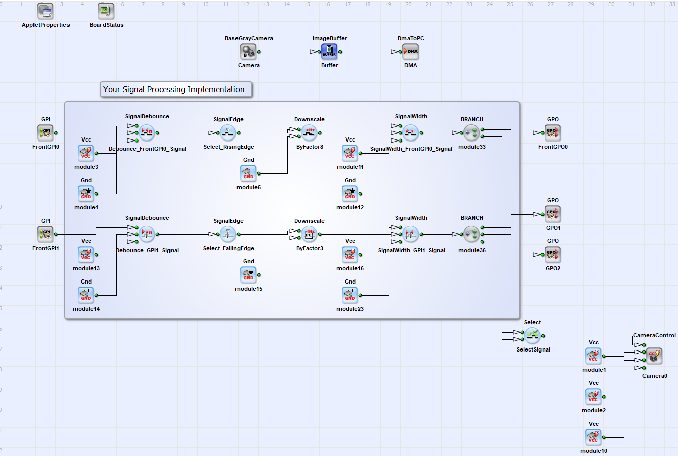
The figure above shows an example on how to implement signal processing. The signal processing functionality you want to implement depends on your specific requirements. To find the right operator for your application, visit the Signal Library. Also choose the Front GPIO according to your requirements.
The example above shows a downscaling functionality for two input signals. Two signals are input from GPI1 and Front GPI0 to the programmable frame grabber. The signals are first debounced, the rising or falling edges are selected, and the signals are then downscaled by a factor 8 or 3. A signal length for both signals is set and the signals are then forwarded to FrontGPO0, GPO1, GPO2 and the camera to control image acquisition.
Using GPI/GPO Operators#
Each trigger IN / trigger OUT pin you want to use on the Front GPIO or the trigger extension board you have to interconnect with an instance of a GPI/GPO operator.
Info
Since operator GPI and operator GPO have the same functionality, in the following both operators are described together.
- Double-click on the operator icon in your design to open the Module Properties window.

The Module Properties window opens:

As you see, the operator has two parameters:
Pin_ID: Parameter Pin_ID allows you to define which individual pin on the selected connector you want to address.ConnectorType: Parameter ConnectorType allows you to define which connector (Front GPIO or trigger extension board via GPIO) you want to address.
Info
For CXP-12 frame grabbers, the ConnectorType parameter is included in the Pin_ID parameter.
Parameter Connector Type#
This parameter allows you to define which group of trigger pins you want to address, the ones provided in the 15-pin D-Sub socket (Front GPIO), or the ones provided on the trigger extension board (GPIO). The parameter has the value range {Front GPIO, GPIO}.
Value Front GPIO#
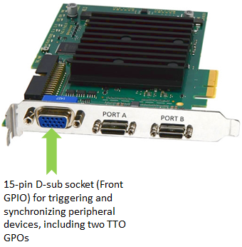
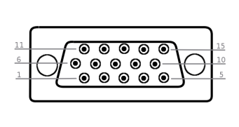
If you select value Front GPIO, you address the following connector (group of trigger pins) on the slot bracket of your programmable frame grabber:
Value GPIO#
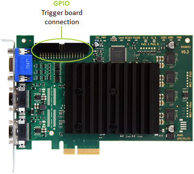
If you select value GPIO, you address the following group of trigger pins on your programmable frame grabber:
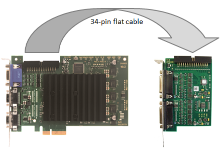
The GPIO is used for connection to a trigger extension board:
Parameter Pin_ID#
This parameter allows you to define which individual pin on the chosen connector (group of trigger pins) you address. The value range of parameter Pin_ID is {0;7} or {0;3} for connector type GPIO or Front GPIO.
Info
The value range of parameter Pin_ID for marathon frame grabbers and operator GPO is {0;1}.
Pin Configuration on the Front GPIO with VisualApplet Operator Reference#
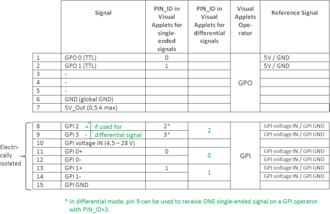
In differential mode, pin 9 can be used to receive ONE single-ended signal on a GPI operator with Pin_ID=3, see Mode "Differential" (Default).
Caution
The frame grabber trigger system needs to get supply voltage on the Voltage IN pins. If you want to connect devices that have no PWR pin, you need to provide the power supply to the Voltage IN pin from an external source.
Trigger INPUT on the Front GPIO#
If you
- are using the
GPIoperator (for defining trigger input signals), - have set parameter
Connector TypetoFront GPIO,
the values of parameter Pin_ID address the following pins:
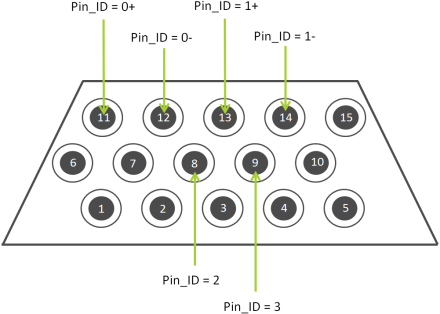
The input (GPI) pins of the Front GPIO are configurable. You can use the six input pins to receive either:
- 3 differential signals, or
- 2 differential signals and 1 single-ended signal , or
- 4 single-ended signals.
To configure the input pins on Front GPIO for a specific signal type (differential or single-ended), you have two modes available:
- Mode
Differential(providing options a and b) - Mode
Single-ended(providing option c)
Default mode for the Front GPIO is mode Differential. How to switch modes, see topic Input Configuration in the frame grabbers` manual.
Caution
In default configuration, the GPIO pins of the Front GPIO offer:
- 3 differential input signals or 2 differential and 1 single-ended input signal in pull-up mode
- Two TTL output signals
If you need another configuration of the input signals, i.e.:
- Pull-down mode,
- 4 single-ended signals (and no differential signals),
you can easily configure the GPIs according to your needs. For configuration, you use a command line tool which has been installed on your system together with the Framegrabber SDK.
Mode Differential (Default)#
In mode Differential (default), all the six input pins of the Front GPIO are configured to receive differential signals:
- Pins 8/9 -> 1 differential signal
- Pins 11/12 -> 1 differential signal
- Pins 13/14 -> 1 differential signal
Alternatively, you can use pin pair 8/9 (in mode Differential) for receiving one single-ended signal:
- Pin 9 -> 1 single-ended signal
- Pins 11/12 -> 1 differential signal
- Pins 13/14 -> 1 differential signal
Individual Pins in Mode Differential:
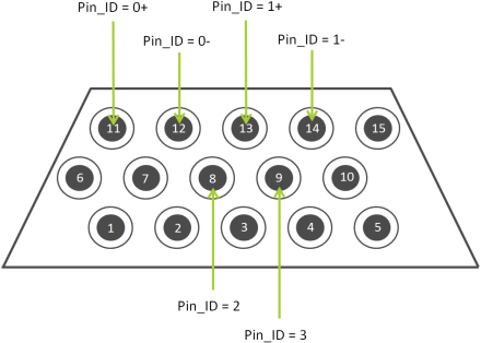
Pins 11 and 12:
- The incoming signals on pins 11 and 12 are interpreted as one differential signal (pin 11 with the +, pin 12 with the - value).
- To receive this differential signal within VisualApplets, use a GPI operator instance with Pin_ID = 0.
Pins 13 and 14:
- The incoming signals on pins 13 and 14 are interpreted as one differential signal (pin 13 with the +, pin 14 with the - value) .
- To receive this differential signal within VisualApplets, use a GPI operator instance with Pin_ID = 1.
Pins 8 and 9:
- The incoming signals on pins 8 and 9 are interpreted as one differential signal (pin 8 with the +, pin 9 with the - value) .
- To receive this differential signal within VisualApplets, use a GPI operator instance with Pin_ID = 2.
Alternatively, you can use pin pair 8/9 for receiving one single-ended signal (although in mode Differential): In this case,
- you connect the single-ended incoming signal to the physical pin 9.
- To receive this single-ended signal within VisualApplets, use a GPI operator instance with Pin_ID = 3.
Mode Single-Ended#
In mode Single-ended (configurable), the six input pins of the Front GPIO are configured to receive 4 single-ended signals:
- Pin 8 -> 1 single-ended signal
- Pin 9 -> 1 single-ended signal
- Pin 11 -> 1 single-ended signal
- Pin 13 -> 1 single-ended signal
Individual Pins in Mode Single-ended:
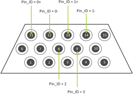
Signals on Pin 11 and 12:
- The incoming signal on pin 11 is interpreted as a single-ended signal.
- To receive this single-ended signal within VisualApplets, use a GPI operator instance with Pin_ID = 0.
- Pin 12 is not used in mode
Single-ended.
Signals on Pin 13 and 14:
- The incoming signal on pin 13 is interpreted as a single-ended signal.
- To receive this single-ended signal within VisualApplets, use a GPI operator instance with Pin_ID = 1.
- Pin 14 is not used in mode
Single-ended.
Pins 8 and 9:
- The incoming signals on pins 8 and 9 are interpreted as two single-ended signals.
-
To receive these single-ended signals within VisualApplets, use
- a GPI operator instance with Pin_ID = 2 for pin 8, and
- a GPI operator instance with Pin_ID = 3 for pin 9.
Trigger OUTPUT TTL on the Front GPIO#
If you
- use the GPO operator for defining trigger output signals,
- you have set parameter Connector Type to Front GPIO,
the values of parameter Pin_ID address the following pins:
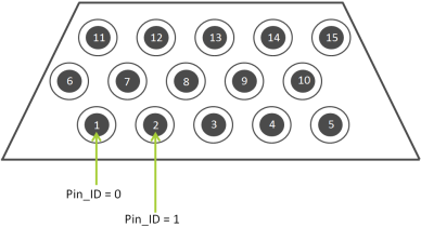
These two pins are sending TTL signals (5 V).
Outgoing TTL signals on Front GPIO (5 V):

Trigger Signals Addressing the Trigger Extension Boards (via GPIO)#
The GPIO connector is the physical trigger interface of programmable frame grabbers that is designed for connection to a trigger extension board:
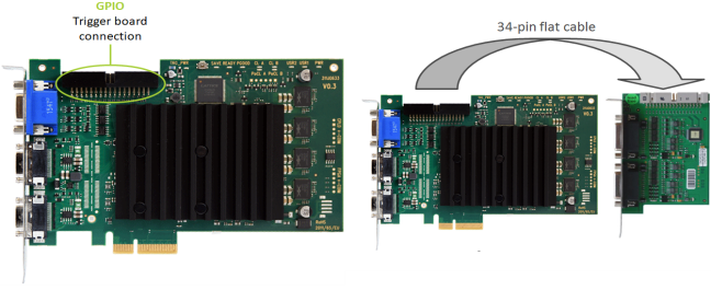
The GPIO connector, i.e., each trigger extension board, offers
- 8 digital inputs (IN 0 - 7) (8 single-ended signals or 4 differential signals)
- 8 digital outputs (OUT 0 - 7)
The eight inputs have the indices 0 to 7. The eight outputs also have indices from 0 to 7.
For more information about the pin layout, see Pin Layout on SUB-D15 - TTL Trigger Board or PIN Layout Opto-Coupled Trigger 5 - Opto-Coupled Trigger 5 Board extension boards.
Pin_ID Assignment on TTL Trigger Extension Boards#
Port A#
| Pin Number | Pin_ID in Visual Applets |
|---|---|
| 1 | 0 |
| 2 | 1 |
| 3 | 2 |
| 4 | 3 |
| 5 | |
| 6 | |
| 7 | |
| 8 | |
| 9 | |
| 10 | |
| 11 | 0 |
| 12 | 1 |
| 13 | 2 |
| 14 | 3 |
| 15 | 0 |
Port B#
| Pin Number | Pin_ID in Visual Applets(single-ended-signals) |
|---|---|
| 1 | 4 |
| 2 | 5 |
| 3 | 6 |
| 4 | 7 |
| 5 | |
| 6 | |
| 7 | |
| 8 | |
| 9 | |
| 10 | |
| 11 | 4 |
| 12 | 5 |
| 13 | 6 |
| 14 | 7 |
| 15 |
Pin_ID Assignment on OPTO Trigger 5 Extension Boards#
Port A#
| Pin Number | Pin_ID in Visual Applets(single-ended-signals) | Pin_ID in Visual Applets(differential signals) |
|---|---|---|
| 1 | 0 | |
| 2 | 1 | |
| 3 | 2 | |
| 4 | 3 | |
| 5 | ||
| 6 | ||
| 7 | ||
| 8 | ||
| 9 | ||
| 10 | ||
| 11 | 0 | 0 |
| 12 | 1 | 0 |
| 13 | 2 | 2 |
| 14 | 3 | 2 |
| 15 |
Port B#
| Pin Number | Pin_ID in Visual Applets(single-ended-signals) | Pin_ID in Visual Applets(differential signals) |
|---|---|---|
| 1 | 4 | |
| 2 | 5 | |
| 3 | 6 | |
| 4 | 7 | |
| 5 | ||
| 6 | ||
| 7 | ||
| 8 | ||
| 9 | ||
| 10 | ||
| 11 | 4 | 4 |
| 12 | 5 | 4 |
| 13 | 6 | 6 |
| 14 | 7 | 6 |
| 15 |
Configuring the Trigger System#
You can access the trigger configuration via two ways:
- microDisplay X: Here, you can enter trigger parameter values via GUI to check the outcome of specific configurations.
- SDK: For implementing the frame grabber programming interface into a specific image processing software application.
The demands on the trigger system vary, depending on your application:
- For Area Scan, only one trigger type (frame trigger) is required.
- For Line Scan, two trigger types are required: Line trigger (sends a trigger pulse for each line) and frame trigger. In a line scan application, the frame trigger controls how many lines are appended to an image.
You may find further information on how to trigger area and line scan cameras here.
Info
For further information about the frame grabber trigger system, refer to topic GPIO Connectors.
Info
For information which parameters are available (and which effects specific settings may cause), refer to the documentation of the applet you are using.
Running Your Applet on Hardware#
Prerequisites:
- Your programmable frame grabber is installed on your system as described in topic Connecting Frame Grabbers.
- The Basler Framegrabber SDK is installed on your system as described at Installing the Framegrabber SDK.
Before you can run your applet on your programmable frame grabber, you have to copy your *.hap file (applet) into the Basler Framegrabber SDK installation on your host PC and flash it onto your programmable frame grabber.
Info
Flashing is only required for marathon frame grabbers.
You find detailed information on how to translate a VisualApplets design to a hardware applet under Hardware Applet: From Idea to Application.
-
Copy the
*.hapfile that you have built in VisualApplets into the directory[Framegrabber SDK installation directory]/Hardware Applets/[frame grabber model]. If there is no subdirectory with the programmable frame grabber model name, create it. If you have used the default settings in VisualApplets, you will find your*.hapfile in your VisualApplets installation directory, subdirectoryDesigns. -
Install your applet on your programmable frame grabber as described in Flashing.
After you have done this, you can:
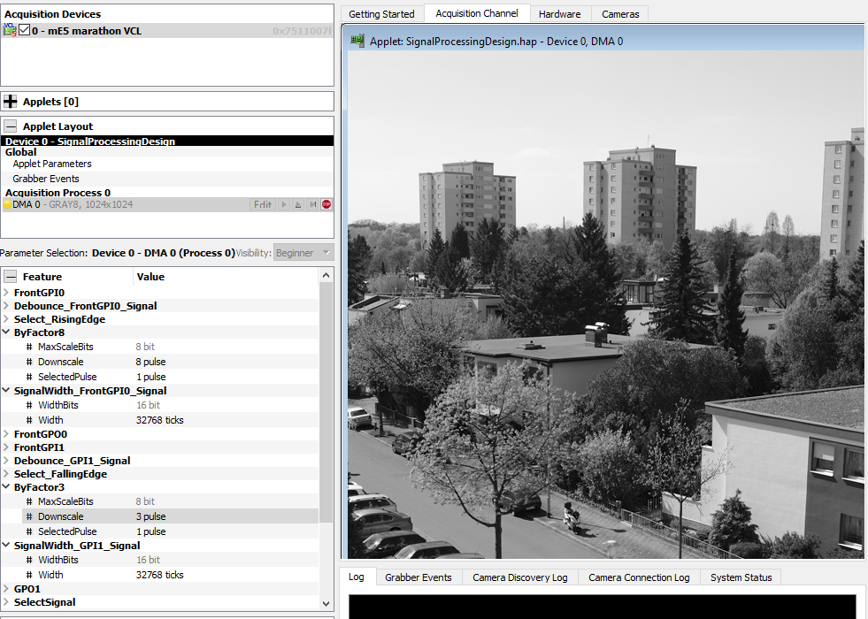
- Test your applet and directly see image processing results of your applet with the Basler tool microDisplay X, which comes as part of the Framegrabber SDK. See the topic Configuring the Applet (microDisplay X).
Example: When you load the hardware applet of the signal processing example design into microDisplay X, you can set the dynamic parameters like the downscaling factor and the signal width in the parameter tree as shown in the figure below.
Starting the Applet in Your Own Software#
To start using the applet in your own software:
- On the Basler application programming interface, use the call
Fg_Initto start the applet. Specify the path to the location of the*.hapfile you created with VisualApplets.
For a detailed description and reference of all available function calls, see the Framegrabber API Manual and the Framegrabber API Function Reference.
As base of a C++ SDK you can use the VisualApplets internal SDK code generator, which you find in the icon menu or under Build and Generate SDK example in VisualApplets. This function automatically generates the corresponding CMake File and the VisualStudio project files (see also Hardware Applet: From Idea to Application).
The automatic SDK code contains the following functional blocks, which are necessary for image acquisition and parameter configuration:
- Frame grabber initialization
- Allocation of memory for buffer(s)
- Definition of
GetandSetparameters - Creation of the display(s)
- Start of acquisition at applet and camera for each present port
- Grabbing images
- Stop of acquisition
- Closing the display
- Release of memory for buffer(s)
- Frame grabber uninitialization
In the following you can see the example C++ Framegrabber API code for the signal processing example.
- Frame Grabber initialization and allocation of memory for buffer(s):
int main ()
{

    // ---------------------------------------------------------------------------
    // Frame Grabber: Initialization
    // ---------------------------------------------------------------------------


    int nrOfCycles = 5000; // Acquire 5000 frames, TODO: insert the number according to your needs
    unsigned int boardIndex = 0; // TODO: Use the correct board index at multi frame grabber systems
    int rc = 0; // return code

    Fg_Struct* fg = Fg_Init("SignalProcessingDesign.hap", boardIndex);
    if(fg == NULL){
        fprintf(stderr, "Error in Fg_Init(): %s\n", Fg_getLastErrorDescription(NULL));
        fprintf(stderr, "Press <Return> to continue...\n");
        getchar();
        return -1;
    }

    int nrOfParameter = Fg_getNrOfParameter(fg);
    fprintf(stderr, "No. of Parameter: %d\n", nrOfParameter);

    int i;
    for (i = 0; i < nrOfParameter; i++) {
        const char *name = Fg_getParameterName(fg,i);
        fprintf(stderr," Param %d: %s,%x\n",i,name,Fg_getParameterId(fg,i));
    }


    / ---------------------------------------------------------------------------
    // Frame Grabber: Allocate memory for buffer(s)
    // ---------------------------------------------------------------------------


    // Feature Cnt 0,0
    int width0 = 1024;
    int height0 = 1024;
    int byteWidth0 = 1;
    size_t bufSize0 = width0 * height0 * (size_t)byteWidth0;
    const unsigned int mem0_bufs = 4;
    dma_mem *pmem0 = Fg_AllocMemEx(fg, bufSize0 * mem0_bufs, mem0_bufs);
    if(pmem0 == NULL){
        fprintf(stderr, "Error in Fg_AllocMemEx(): %s\n", Fg_getLastErrorDescription(fg));
        Fg_FreeGrabber(fg);
        fg = NULL;
        fprintf(stderr, "Press <Return> to continue...\n");
        getchar();
        return -1;
    }
- Extract of the
GetandSetparameter section. Here you can see how to set the dynamic parameters. The following code shows how to set the downscale factor and how to select a specific pulse as parameter of operatorDevice1_Process0_ByFactor8:
// ---------------------------------------------------------------------------
// Frame Grabber: Get* and Set* parameters for Process0
// ---------------------------------------------------------------------------


/*============ Downscale : ByFactor8 ============== */


int Device1_Process0_ByFactor8_Downscale_Id = Fg_getParameterIdByName(fg, "Device1_Process0_ByFactor8_Downscale");
if(Device1_Process0_ByFactor8_Downscale_Id <= 0) {
    fprintf(stderr, "\n");
    fprintf(stderr, "Error in Fg_getParameterIdByName(Device1_Process0_ByFactor8_Downscale): %s (%d)\n", Fg_getLastErrorDescription(fg), Device1_Process0_ByFactor8_Downscale_Id);
    fprintf(stderr, "Press <Return> to continue...\n");
    getchar();
}

unsigned int Device1_Process0_ByFactor8_Downscale;
Device1_Process0_ByFactor8_Downscale = 8;
rc = Fg_setParameterWithType(fg, Device1_Process0_ByFactor8_Downscale_Id, Device1_Process0_ByFactor8_Downscale, 0);
if(rc < 0) {
    fprintf(stderr, "\n");
    fprintf(stderr, "Error in Fg_setParameterWithType(Device1_Process0_ByFactor8_Downscale_Id): %s (%d)\n", Fg_getLastErrorDescription(fg), rc);
    fprintf(stderr, "Press <Return> to continue...\n");
    getchar();
}

int Device1_Process0_ByFactor8_SelectedPulse_Id = Fg_getParameterIdByName(fg, "Device1_Process0_ByFactor8_SelectedPulse");
if(Device1_Process0_ByFactor8_SelectedPulse_Id <= 0) {
    fprintf(stderr, "\n");
    fprintf(stderr, "Error in Fg_getParameterIdByName(Device1_Process0_ByFactor8_SelectedPulse): %s (%d)\n", Fg_getLastErrorDescription(fg), Device1_Process0_ByFactor8_SelectedPulse_Id);
    fprintf(stderr, "Press <Return> to continue...\n");
    getchar();
}

unsigned int Device1_Process0_ByFactor8_SelectedPulse;
Device1_Process0_ByFactor8_SelectedPulse = 1;
rc = Fg_setParameterWithType(fg, Device1_Process0_ByFactor8_SelectedPulse_Id, Device1_Process0_ByFactor8_SelectedPulse, 0);
if(rc < 0) {
    fprintf(stderr, "\n");
    fprintf(stderr, "Error in Fg_setParameterWithType(Device1_Process0_ByFactor8_SelectedPulse_Id): %s (%d)\n", Fg_getLastErrorDescription(fg), rc);
    fprintf(stderr, "Press <Return> to continue...\n");
    getchar();
}
Info
You may delete all parameters that are not relevant for parameter setting during acquisition from the automatically generated C++ Framegrabber API code. Only keep the parameters you need to configure during acquisition.
- Create the display(s), start of acquisition, and grab images:
// ---------------------------------------------------------------------------
// Frame Grabber: Create the display(s)
// ---------------------------------------------------------------------------

int id0 = CreateDisplay(8 * byteWidth0, width0, height0);
if(id0 < 0) {
    fprintf(stderr, "Error in CreateDisplay(): %s (%d)\n", Fg_getLastErrorDescription(fg), id0);
    Fg_FreeMemEx(fg, pmem0);
    pmem0 = NULL;
    Fg_FreeGrabber(fg);
    fg = NULL;
    fprintf(stderr, "Press <Return> to continue...\n");
    getchar();
    return id0;
}
SetBufferWidth(id0, width0, height0);


// ---------------------------------------------------------------------------
// Frame Grabber: Start acquisition at applet and camera for each present port
// ---------------------------------------------------------------------------

rc = Fg_AcquireEx(fg, 0, nrOfCycles, ACQ_STANDARD, pmem0);
if(rc != 0) {
    fprintf(stderr, "Error in Fg_AcquireEx() for channel 0: %s\n", Fg_getErrorDescription(fg, rc));
    CloseDisplay(id0);
    Fg_FreeMemEx(fg, pmem0);
    pmem0 = NULL;
    Fg_FreeGrabber(fg);
    fg = NULL;
    fprintf(stderr, "Press <Return> to continue...\n");
    getchar();
    return rc;
}

// ---------------------------------------------------------------------------
// Frame Grabber: Grab images
// ---------------------------------------------------------------------------

frameindex_t frameNo0 = 0;
for(i = 1; i <= nrOfCycles; ++i){
frameNo0 = Fg_getLastPicNumberBlockingEx(fg, frameNo0 + 1, 0, 5, pmem0);
    if(frameNo0 < 0) {
        fprintf(stderr, "Error in Fg_getLastPicNumberBlockingEx(): %s (%d)\n", Fg_getLastErrorDescription(fg), frameNo0);
        fprintf(stderr, "Press <Return> to continue...\n");
        getchar();
        break;
    } else {
        fprintf(stderr, "grabbed image %d\n", frameNo0 );
    }

    void *iPtr0 = Fg_getImagePtrEx(fg, frameNo0, 0, pmem0);
    if(iPtr0 == NULL) {
        fprintf(stderr, "Error in Fg_getImagePtrEx(): %s\n", Fg_getLastErrorDescription(fg));
        Fg_stopAcquireEx(fg, 0, pmem0, 0);
        CloseDisplay(id0);
        Fg_FreeMemEx(fg, pmem0);
        pmem0 = NULL;
        Fg_FreeGrabber(fg);
        fg = NULL;
        fprintf(stderr, "Press <Return> to continue...\n");
        getchar();
        return -1;
    }
    DrawBuffer(id0, iPtr0, frameNo0, "");
}
- Stop acquisition, close the display, release of memory for buffer(s):
// ---------------------------------------------------------------------------
// Frame Grabber: Stop acquisition
// ---------------------------------------------------------------------------

rc = Fg_stopAcquireEx(fg, 0, pmem0, 0);
if(rc < 0) {
    fprintf(stderr, "Error in Fg_stopAcquireEx(): %s (%d)\n", Fg_getLastErrorDescription(fg), rc);
    fprintf(stderr, "Press <Return> to continue...\n");
    getchar();
}


// ---------------------------------------------------------------------------
// Frame Grabber: Close the display
// ---------------------------------------------------------------------------

CloseDisplay(id0);


// ---------------------------------------------------------------------------
// Frame Grabber: Release the memory for buffer(s)
// ---------------------------------------------------------------------------

rc = Fg_FreeMemEx(fg, pmem0);
if(rc < 0) {
    fprintf(stderr, "Error in Fg_FreeMemEx(): %s (%d)\n", Fg_getLastErrorDescription(fg), rc);
    fprintf(stderr, "Press <Return> to continue...\n");
    getchar();
}
pmem0 = NULL;


// ---------------------------------------------------------------------------
// Frame Grabber: Uninitialization
// ---------------------------------------------------------------------------

rc = Fg_FreeGrabber(fg);
if(rc < 0) {
    fprintf(stderr, "Error in Fg_FreeGrabber(): %s\n", Fg_getLastErrorDescription(NULL));
    fprintf(stderr, "Press <Return> to continue...\n");
    getchar();
}
fg = NULL;


fprintf(stderr, "Press <Return> to exit...\n");
getchar();

return (0);
}
You may integrate this example code into a larger SDK environment.