Table of Contents
In this Application Note you will learn how to design and create an image processing application (=applet) in VisualApplets and how to use it on a frame grabber. You will also learn how to use this applet during runtime using microDisplay and Framegrabber API and how to configure parameters of your applet in this software. You find an introduction how to design, build and use an applet during runtime in microDisplay at Getting Started. In this Application Note you will learn the above mentioned phases of applet development and usage with the example of a Sobel edge filter application.
The workflow is as follows:
-
Designing an applet in VisualApplets.
-
Simulating the applet in VisualApplets and performing a Design Rules Check (DRC).
-
Building the applet.
-
For mE5 platforms: Flashing the applet.
-
Using the applet on the hardware via microDisplay or Framegrabber API.
The design phase of an applet takes place in VisualApplets. To open VisualApplets,
click on the file VisualApplets.exe in the
bin folder in the VisualApplets installation directory, or
the VisualApplets program icon in the Windows Start menu or on the icon on your
desktop.
-
At first, the VisualApplets main window opens up with no project loaded.
-
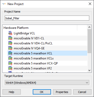
Click on File+New ( Ctrl+N ) or use the icon from the icon bar. A window opens up which allows you to specify project name, target hardware platform, and target runtime. You can always change these settings later on.
-
To follow the example here, use the following settings:
-
Confirm your settings by clicking .
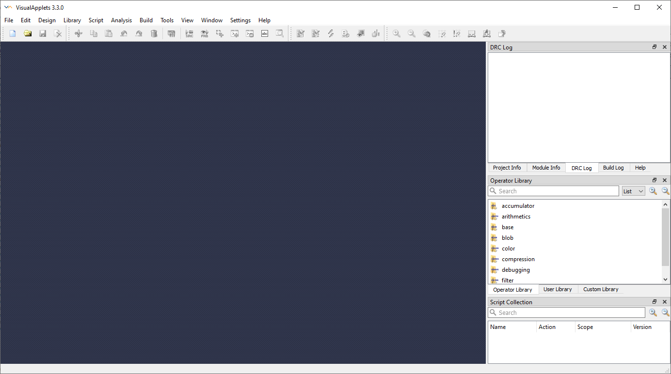
VisualApplets now starts a new project and you see a blank design window in the center of the program window. In the tab on the right, information regarding the current project, such as project name, target hardware, target platform etc. is displayed.
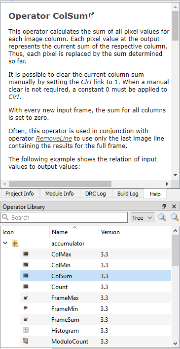
In VisualApplets, image processing operations are represented by operators. You find all these operators in the on the right side of the VisualApplets design window. You can very easily place operators into the design window using drag-and-drop.
An instance of an operator in the design is called a module. Operators can have input and output ports. Operators in a design (i.e., modules) can be connected using these ports. Connections between modules are called links which are represented in the design window by arrows. These modules and links represent the image- (or signal-) processing pipeline. Hence, the order of operations is determined by the order of modules.
The operators and links have properties, which describe the settings relevant for the current image processing pipeline, like image dimensions. To see and edit these properties, double-click the operators. The properties of the operators are explained in detail in the operator documentation under .
This example implements a Sobel edge filter algorithm.
In the VisualApplets design sample library, there are “ready-to-use" samples for
edge filtering and further image processing applications. You find these design
examples under Examples\Processing in your VisualApplets
installation directory with the corresponding documentation, see Processing Examples. You can use these example designs as base for your own
application.
For the implementation of this sample Sobel filter design, locate the operators in the , drag them into the design and connect them with links as described in the Getting Started section.
You can rename the modules later on for better overview in the design and for better usage during runtime.
Whenever useful, structure the design using HierarchicalBoxes for a better design overview.
And don't forget to save the design from time to time.
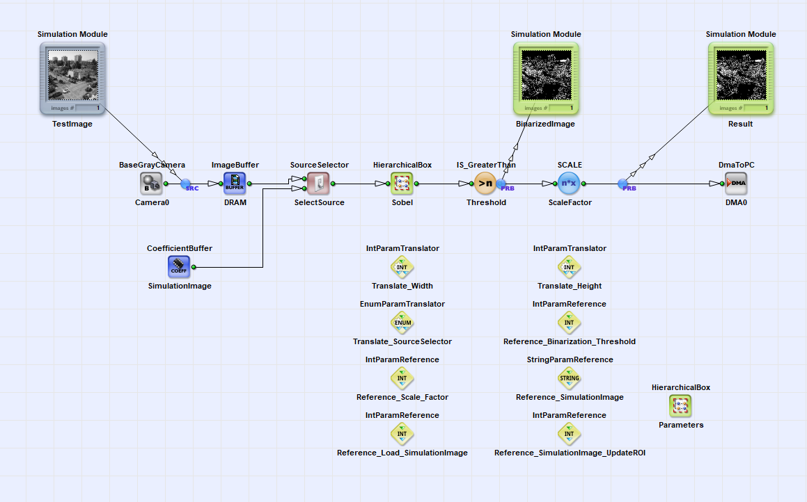
The sample design in this application note consists of the following components as shown in the following figure:
-
A Camera Link grayscale camera interface
-
An image buffer
-
The Sobel edge filter module with edge filtering in x and y direction (based on the example
SobelMultiGradient.vadunderExamples\Processing\Filter\EdgeDetection\Sobel_Multi_Gradientin the VisualApplets installation directory) -
An adjustable binarization threshold and a scale operator for better visualization of the binarized image on the display during runtime
-
The DMA to PC.
You can use the CoefficientBuffer in the design as simulation source for images instead of using the images acquired by a camera. Via the operator SourceSelector you can choose the image input source for the processing pipeline in VisualApplets and during runtime.
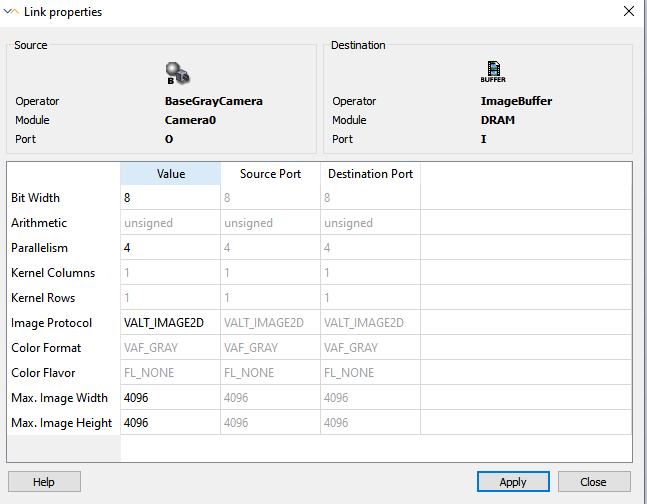
To parameterize the operators and links, you can edit the parameters of each element by double-clicking the element.
Links have properties, which define the properties of the processed images such as maximum image dimensions, the image protocol, the bit width, and a parameter which is related to the maximum possible bandwidth: the parallelism (i.e. numbers of pixel transferred at one design clock cycle). If these links are connected to specific operators (see corresponding operator documentation), e.g. the camera interface operators, you can edit and adjust these properties according to your purpose.
The higher the maximum image dimensions and the parallelism you choose, the higher the FPGA resource consumption is. Therefore, Basler recommends to set these values only as high as necessary in order to save FPGA resources. The link properties can only be changed during design phase in VisualApplets.
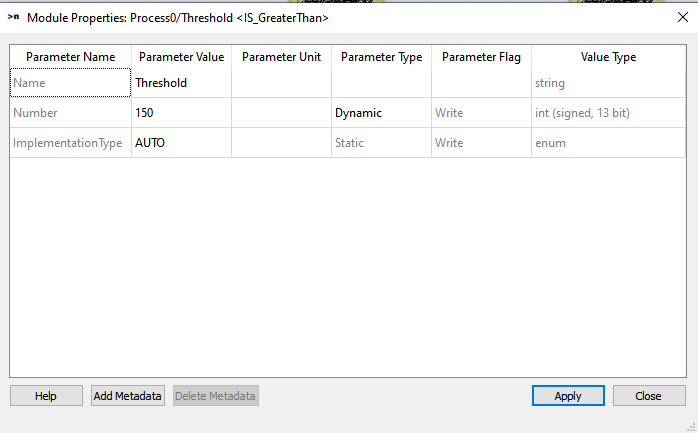
There are two types of operator properties: static and dynamic. You can change static parameters only during design phase in VisualApplets, whereas you can change dynamic parameters during design phase and during runtime. See the screenshot below for examples of static and dynamic parameters for the operator IS_GreaterThan.
In this sample design, set the following parameters:
- Operator IS_GreaterThan:
-
Set the parameter Number to 600.
This identifies the grayscale of the edges. If you want to find out the grayscale of your edges, set a simulation probe before the IS_GreaterThan operator, run a simulation, and zoom into the pixels that contain edges and see which grayscale they have. This is a dynamical paramter, which you can alter during runtime.
- Operator SCALE:
-
Set the parameter ScaleFactor to 255.
This augments the visibility of the edges. This is a dynamical parameter. However, to save FPGA resources, you can set this parameter to Static.
During runtime you can change the dynamic parameters. A common use case is that you have many operators in a design and you need to change the same parameters e.g. the image dimensions for many different operators in the design.
The library Parameters provides operators which enable
accessing different module parameters in a design by controlling only one
parameter. Additionally, these operators also enable that access parameters are
displayed on a specific hierarchy level. These options make parameter
configuration easier during runtime. The example design Sobel_Filter.va
(see Figure 189, 'Example Design Implementation Sobel_Filter.va') uses translate and
reference parameters to easily access image width and height, the image source
selector, the threshold value and the scale factor on the hierarchy level
. For this, create an empty HierarchicalBox,
name it and set the
DisplayHierarchy parameter of the corresponding
translate and reference parameters to . You find a
detailed documentation of the Parameters library in the
corresponding documentation, see Library Parameters.
During design phase the simulation sources and probes are very helpful. Using the simulation sources you can load test images and check your processed image on every link in the processing pipeline within a few moments. Exception: Signals can’t be simulated. Furthermore, the simulation performs a Design Rule Check Level 1 for the formal correctness of the implementation. The simulation result is equivalent to the result during runtime. You find the simulation sources and probes in the icon menu or under Analysis in the text menu in VisualApplets. For a detailed description of the usage of the simulation sources and probes, see the detailed documentation under 'Simulation'.
In Figure 189, 'Example Design Implementation Sobel_Filter.va' you can see a test image
loaded to a simulation source in the example design
Sobel_Filter.va. After threshold and before DMA you can
see the result of the current processing step.
After you have finalized the implementation, it is recommended to perform a Design Rule Check Level 1 and 2. To perform a Design Rule Check Level 1 and 2, select Analysis+Design Rules Check Level 1 and 2 or use the icon from the icon bar.
Design Rule Check Level 1 reports formal errors in the implementation and their exact location in the design. You must correct these errors before the design can be translated to a hardware applet.
Design Rule Check Level 2 additionally gives information about the estimated FPGA resources used in the design. With this information you can check, whether enough FPGA resources are available for your image processing implementation. If the resources exceed 100% of one of the FPGA resources, you need to redesign your implementation to save resources.
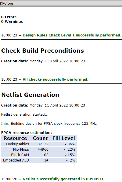
In Figure 192, 'Design Rule Check 1 and 2 for the Example Design
Sobel_Filter.va' the result of Design Rule Check 1 and 2 is
shown: Everything is designed correctly and about 36% of the available Lookup
Tables, 22% FlipFlops, 15 % Block RAM and 2 % of the available embedded ALUs are
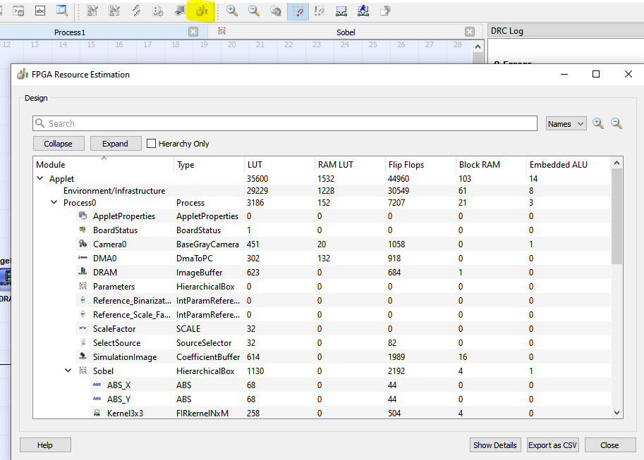
used. You can see a detailed overview on how many FPGA resources each element in
the design consumes (see Figure 193, 'FPGA Resource Estimation') under Analysis+FPGA Resource Estimation
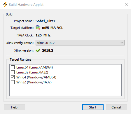
The hardware applet build process can only be performed if the XILINX tools are
properly installed. Under https://docs.baslerweb.com/visualapplets/installing-visualapplets#which-xilinx-toolchain-and-version-for-which-frame-grabber-platform you can find a detailed overview, which Xilinx versions is suitable for your
frame grabber platform. In this sample design Sobel_Filter.va
the microEnable 5 marathon VCL platform is selected. Thus, Xilinx ISE version 14.7
or Vivado versions between 2016.1 and 2020.1 are suitable.
Now you have finished the example design Sobel_Filter.va and
want to translate the design into a hardware applet. For this translation process,
called build you need to select the correct Xilinx build
settings. Open Settings+Build Settings, and select the batch file settings64.bat of your
corresponding Xilinx version (recommended: Xilinx Vivado 2018.2) from your file
system and confirm with OK. You find a detailed description of editing the build
settings under 'Build Settings'.
VisualApplets now uses the Xilinx tools to translate the application into the FPGA
bitstream, i.e., the program or applet.
The duration of this process depends on the complexity of the design. The build of
highly complex designs might take several hours. For this example implementation
Sobel_Filter.va, the build time is about 15 minutes. After
successful build, the applet is fully generated. The name of the applet
(*.hap file) is the same as the name of the design file
(*.va): Sobel_Filter.hap
To run an applet in hardware on a frame grabber, a programmable (V Series) frame grabber (hardware) needs to be installed on the system. Furthermore, the Framegrabber SDK software needs to be installed on the PC. For this example applet for the microEnable 5 marathon VCL, the latest possible Framegrabber SDK version is 5.7.
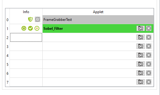
If, like in this example, you use a microEnable 5 marathon frame grabber, you need to flash your frame grabber with the new applet using microDiagnostics.
If you are going to use the new applet on a microEnable IV frame grabber or a frame grabber of the latest CXP 12 series, just skip this section.
To flash the frame grabber, perform the following steps:
-
Start the tool microDiagnostics under
binin the Framegrabber SDK installation directory. -
Select your frame grabber.
-
Select in the left side of the dialog.
-
Assign your hardware applet to one of the displayed partitions (0 to 7): Go to the directory, where the created hardware applet is located and select the file.
-
Click

-
Wait until the new firmware is completely installed. When flashing is completed, you get a message in microDiagnostics.
-
Follow the instructions in the message.
To test your applet Sobel_Filter.hap and to set some first
parameters,use the program microDisplay. Following steps are necessary to load an
applet:
-
Save the applet (here:
Sobel_Filter.hap) underHardware Applets\<your frame grabber>(here: mE5-MA-VCL) in the Framegrabber SDK installation directory. -
Start microDisplay from the
binfolder in the Framegrabber SDK installation directory. -
In microDisplay, select the frame grabber you want to use under . Immediately, all applets available for the selected frame grabber are displayed.
-
Select the
*.hapfile you want to use (here:Sobel_Filter.hap) with double-click.
After loading the applet, you can see the parameter tree and the image acquisition
window in microDisplay. Below, a screenshot of the applet
Sobel_Filter.hap loaded in microDisplay is shown.
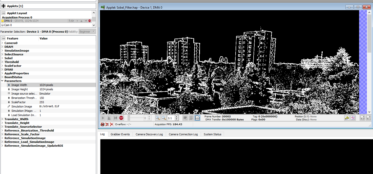
On the left side, the parameter tree is displayed. These parameters are equivalent to the operator names during design phase in VisualApplets. It is important to use a good naming of the operators, in order to find the correct parameters you want to adjust for acquisition. Dynamic parameters are adjustable during runtime. There are two kinds of dynamic parameters: Those parameters, which are only adjustable before start of acquisition (e.g. DMA dimensions) and those, which can be adjusted even during image acquisition (e.g. threshold values of operator IS_GreaterThan).
In this example, you perform the image acquisition using an image from a simulator source and set the binarization threshold to value 150. If you have integrated the parameters of the Parameters library during design phase in VisualApplets, you can set all relevant dynamic parameters under the hierarchy level in the parameter tree. Otherwise, you need to step though the different hierarchy levels to find the correct parameters we want to set.
In this example, go to the hierarchy level and unfold it:
-
Right mouse-click the . As a result, you can select the example image you want to use for image acquisition.
-
Load this image by clicking .
-
Set the parameter ImageSource selector to Simulator and the Binarization Threshold to value 150.
-
Set the image dimensions to 1024x1024 pixels.
After you have set these parameters (or all parameters relevant for your applet), you can start the acquisition. Here you can select between continuous grabbing, grabbing of a sequence or a single frame. To stop the continuous grabbing, click on the Stop button. For the case of a multi process design, you can start and stop the the acquisition of the single processes separately.
For a detailed description of the applet configuration and acquisition with microDisplay, see https://docs.baslerweb.com/frame-grabbers/what-is-micro-display-x.
Instead of performing the applet configuration and acquisition in mircoDisplay X you can alternatively integrate them in your own SDK environment. In this section you find an introduction to the basic functionalities of the relevant SDK componets for image acquisition and configuration.
As base of a C++ SDK you can use the VisualApplets internal SDK code generator, which you find the icon menu or under Build+Generate SDK Example in VisualApplets. This function automatically generates the corresponding CMake File and the VisualStudio project files, which you can use as base for your SDK code.
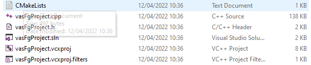
The generated C++ code in the project file vasFgProject.cpp
contains the following code components:
-
Frame Grabber: Initialization
Definition of number of acquisition cycles, definition of board index, call of function
Fg_Init("Sobel_Filter.hap",
                                                                boardIndex)
to start the applet. -
Allocation of memory for buffers for acquisition.
function:
Fg_AllocMemEx(fg, ..., ...) -
Frame Grabber: Get* and Set* parameters for Process0
functions:
Fg_setParameterWithType(fg, ..., ..., ...)andFg_getParameterWithType(fg, ..., ..., ...)Here all parameters contained in the design are listed. Basler recommends to delete all parameters, which are not necessary for adjustment during runtime, for better overview.
-
Create the display(s)
function
CreateDisplay() -
Start acquisition at applet and camera for each present port:
function:
Fg_AcquireEx(fg, 0, nrOfCycles,
                                                            ...,...)
; -
Grab images:
function:
Fg_getLastPicNumberBlockingEx(fg, ..., ..., ...,
                                                                ...)
; -
Stop acquisition
Function
Fg_stopAcquireEx(fg, .., .., ...) -
Close the display
function
CloseDisplay(...); -
Release the memory for buffer(s)
function
Fg_FreeMemEx(fg, ..); -
Frame Grabber Uninitialization
function
Fg_FreeGrabber(fg);
A detailed description and explanation of the SDK functions is available at https://docs.baslerweb.com/frame-grabbers/sdk/basler__fg_8h.html
An introduction to the Framegrabber API is available at https://docs.baslerweb.com/frame-grabbers/framegrabber-api.html.
You can integrate the generated sample SDK code into a larger SDK environment for the further software processing of the frame grabber (pre-)processed images.
