Image Alignment vTool#
Some vTools, e.g., the Measurements Basic vTool, rely on the object to be measured to appear at the same position as the object in the model.
Using the Image Alignment vTool between a Matching tool, e.g., Geometric Pattern Matching vTool, and a Measurements vTool gives you more flexibility regarding the position of objects. It can align an object in the input image with the reference object used during matching. This way, you can measure objects at different positions.
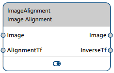
The Image Alignment vTool accepts an image via the Image input pin and alignment transformation data from the Matching tools via the AlignmentTf input pin. It outputs an aligned image via the Image output pin and the data for reversing the transformation via the InverseTf output pin.
How It Works#
The position of the target object in the teaching image used by Matching vTools is the reference position. During operation, the Matching vTools compare the position of the matched object in the input image to the reference position. The result is a relative transformation from the reference position to the actual position. This data is output via the Matching vTool's AlignmentTf output pin.
The Image Alignment vTool accepts the alignment transformation data from the Matching tool via its AlignmentTf input pin. Using this data, it can output an image in which the target object always appears at the same position. The aligned image is output via the Image output pin and can be used by subsequent vTools that require identical positioning of the target object.
The Image Alignment vTool also computes and outputs inverse transformation data via its InverseTf output pin. The inverse transformation data allows the subsequent vTool to output correct position data for the input image instead of the aligned image.
The Matching vTool and the Alignment vTool use the same input image. Alignment works best if the image only contains one target object. While it is possible to fine-tune matching via the Matches and Score options, problems may occur if the score values of target objects are too similar. This could lead to the wrong match being chosen and alignment not working as expected.
Image Alignment Example#
Assume you are a manufacturer of punching dies and want to make sure that the dies you are producing are identical by measuring the gaps between the different square-shaped holes in the die. Because the position of the dies may vary during the inspection process, you use the Geometric Pattern Matching Basic vTool and the Image Alignment vTool in preparation for the actual measuring task using the Measurements Basic vTool.
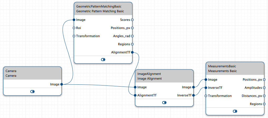
The recipe for this workflow looks like this. Note that the Image output pin of the Camera vTool must be connected to the Image input pins of the Geometric Pattern Matching Basic vTool and the Image Alignment vTool.
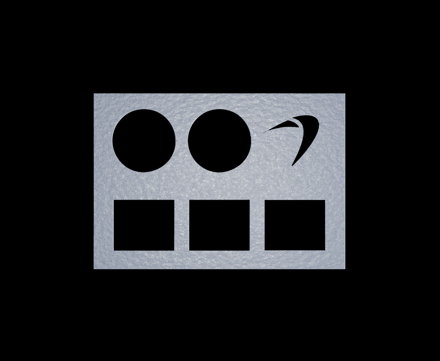
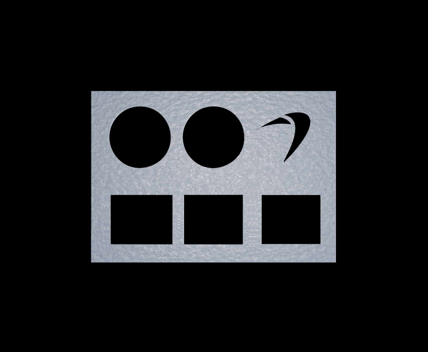
The following image is the template image, i.e., the ideal image that you want to compare against.
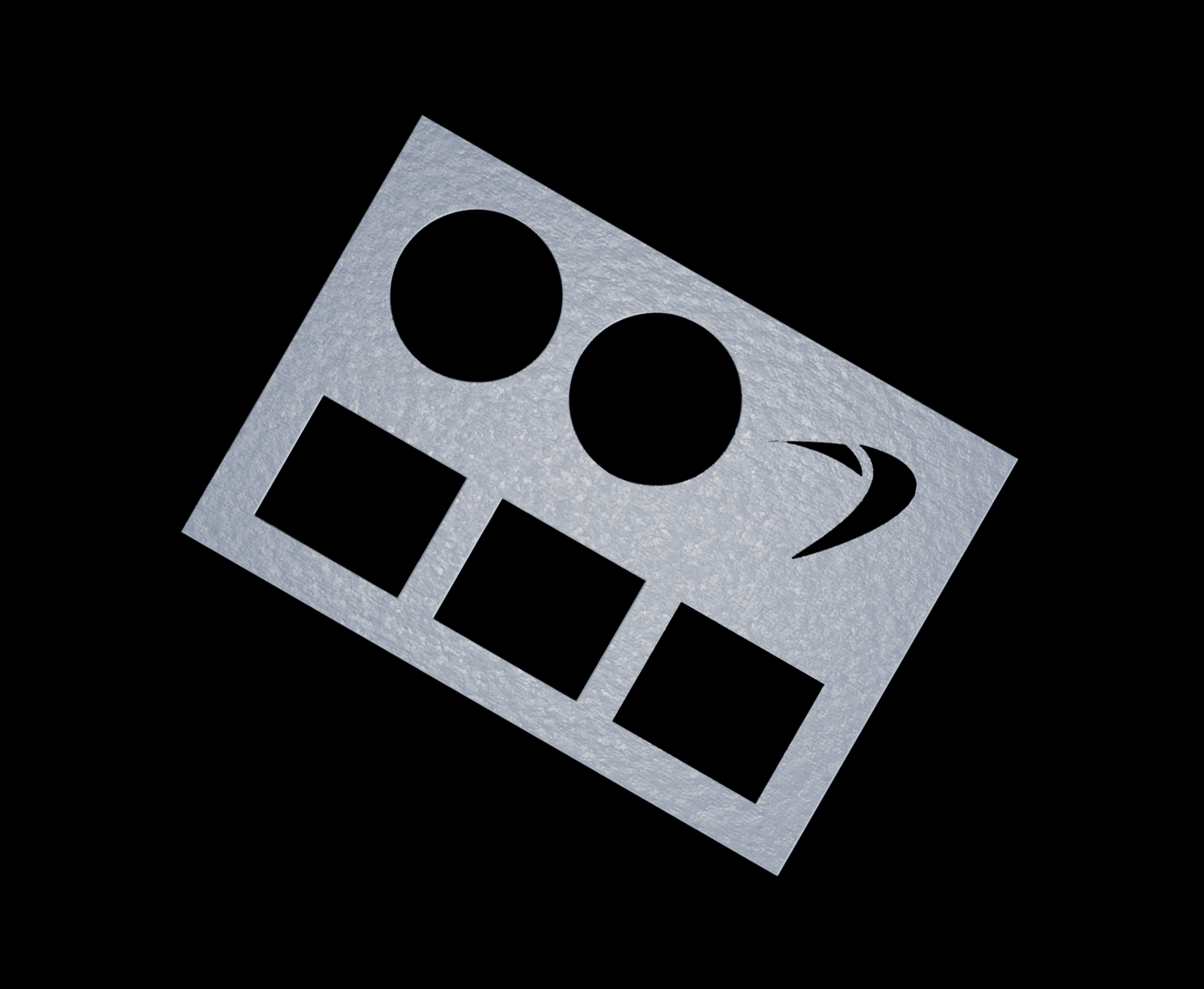
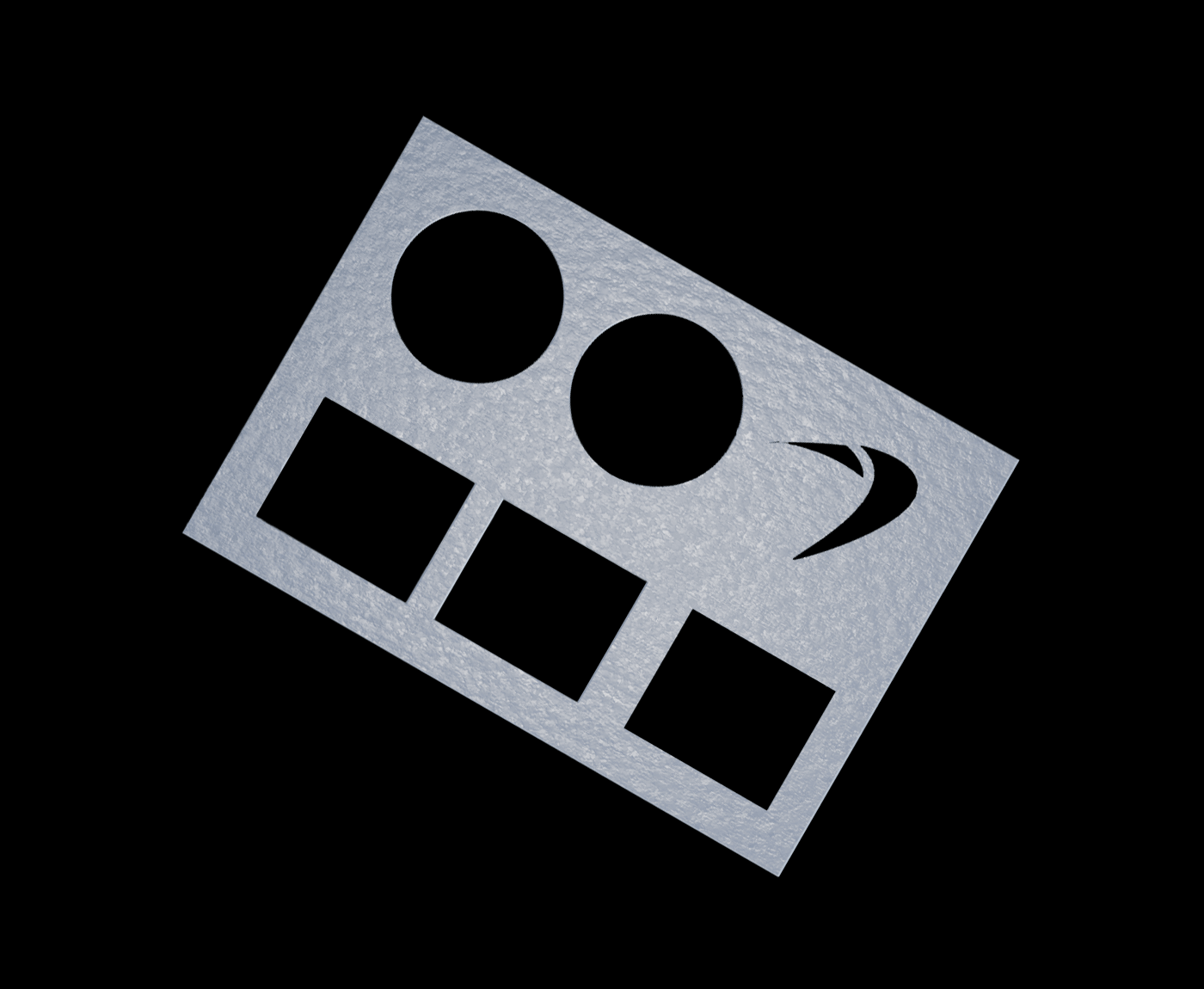
During inspection, you may encounter the following dies that deviate from the template image in certain aspects.
Die with correct gaps but rotated by 30 degrees:
Die in identical position but with incorrect gaps between the holes:
Die with incorrect gaps and rotated by 30 degrees:
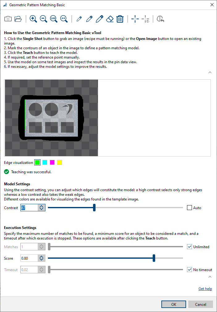
To configure the Geometric Pattern Matching Basic vTool, load the template image, mark the die and teach the model.
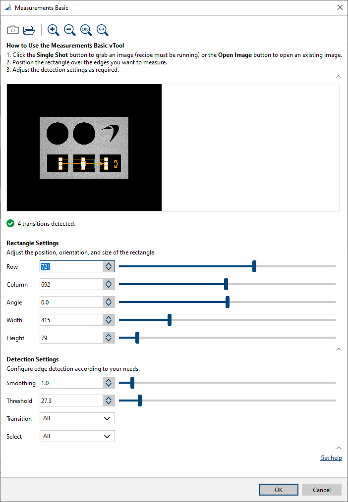
To configure the Measurements Basic vTool, load the template image and configure the settings as shown in the following screenshot.
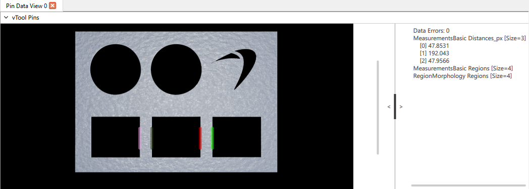
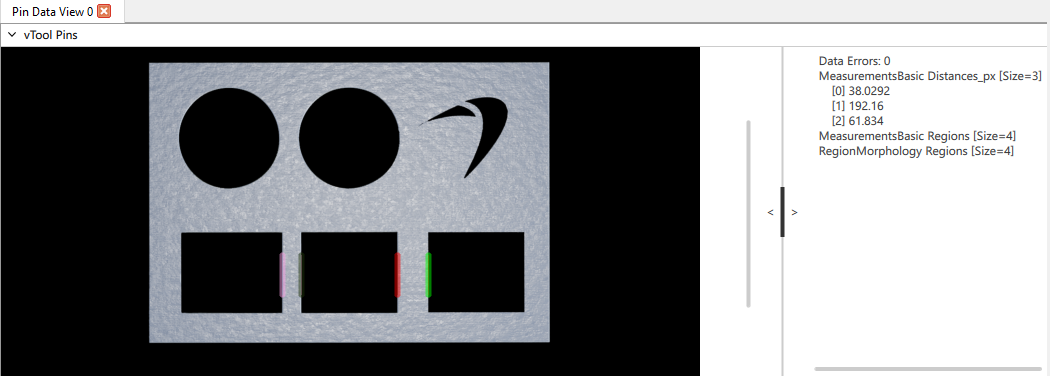
If you run the recipe, the results will look like this.
Die with correct gaps:
Die with incorrect gaps:
Configuring the vTool#
The vTool has no configurable settings.
Inputs#
Image#
Accepts images directly from a Camera vTool or from a vTool that outputs images, e.g., the Image Format Converter vTool.
- Data type: Image
- Image format: 8-bit to 16-bit mono or color images (see Supported Pixel Formats)
AlignmentTf#
Accepts alignment transformation data from any Matching vTool.
- Data type: Transformation Data
Outputs#
Image#
Returns the aligned image. The output image can be used by any vTool accepting images as input. The output image has the same size as the input image.
- Data type: Image
- Image format: Color or mono images (see Supported Pixel Formats)
InverseTf#
Returns the inverse transformation data of the alignment transformation. With this, 2D point coordinates from the coordinate system of the aligned image can be transformed into the coordinate system of the input image.
- Data type: Transformation Data
Supported Pixel Formats#
Depending on the pixel format of the input image, the Image Alignment vTool outputs the following pixel formats:
| Input Pixel Format | Output Pixel Format |
|---|---|
| Bayer GR 8 | BGR 8 Packed |
| Bayer GR 16 | RGB 16 Packed |
| Bayer RG 8 | BGR 8 Packed |
| BGRA 8 Packed | BGRA 8 Packed |
| BGR 8 Packed | BGR 8 Packed |
| Mono 8 | Mono 8 |
| Mono 16 | Mono 16 |
| RGB 8 Packed | RGB 8 Packed |
| RGB 16 Packed | RGB 16 Packed |
| RGB 8 Planar | RGB 8 Packed |
| RGB 16 Planar | RGB 16 Packed |
Related vTools#
Typical Predecessors#
- Camera vTool
- Image Format Converter vTool
- Calibration vTool
- Geometric Pattern Matching vTool
- Template Matching vTool