Bit Arithmetic#
This topic explains how bit widths behave in the FPGA pipeline generated from a VisualApplets design. After you have read this topic, you understand how link bit width limits arithmetic results, how you handle overflow, and how you use cast, clip, and shift operators to control value ranges. You also know how signed and unsigned values differ, how fixed-point numbers work, and how you extract bit fields from wider data words.
Key Terms
For link properties and parameter dependencies, see Parameterization Tutorial topic. For the formal rules behind links, see Rules of Links in the User Manual.
Link Bit Width Limits and Operator Constraints#
Each link between two modules (i.e. instantiated operators) carries a Bit Width property. This property defines how many bits the generated FPGA pipeline uses for each pixel or value on that connection. For color links, the bit width covers all color components together. On links with ImageProtocol = VALT_SIGNAL, the bit width is always 1 bit.
A link supports at most 64 bits per data word. When an operator calculates a wider result, you must clip, cast, or shift the data before the link width exceeds this limit.
Not every operator accepts every bit width. Some operators allow only specific ranges such as 1 to 64 bits, 8 bits, 12 bits, or 16 bits. The Supported Link Format table in the Operator Reference documents the allowed values for each operator. You can also open operator help from the design pane with a right-click on a module and Help, or press F1. This is the same content as in the Operator Reference, provided as in-tool help in VisualApplets.
When a bit width conflict appears, check the output link of the upstream operator first. Adjust the Bit Width link property on an operator that lets you edit it, or insert an operator such as CastBitWidth, ClipHigh, ClipLow, ShiftLeft, or ConvertPixelFormat to change the bit width along the path.
Link properties propagate through the pipeline until an operator changes them. Set the width on the camera output link or insert a bit width operator on the processing path. See Propagation of Link Properties Tutorial topic.
Bit Widths for Arithmetic Operations#
Operators of the Arithmetic library derive the output Bit Width automatically. The Supported Link Format table in the Operator Reference marks these outputs as auto. You usually can't edit these output bit width link properties directly on the link. If you wish to change the bit width manually after the arithmetic operation, use additional operators such as CastBitWidth in combination with ClipHigh, ClipLow, or both. The following arithmetic operators also change the bit width:
Addition and Subtraction#
The ADD operator sums the pixel values on all input links. The SUB operator subtracts the pixel values on the second input from the first input.
VisualApplets sets the output bit width from the input bit width. The result is one bit wider than that maximum. If you mix unsigned and signed inputs on ADD, the output may need one additional bit.

The output bit width must not exceed 64 bits. After ADD or SUB, check the propagated link width on downstream connections.
Multiplication#
The MULT operator multiplies the pixel values at its two inputs. The maximum allowed input bit width at one link is 32 bit. The output bit width equals the sum of the two input bit widths. An 8-bit value multiplied by an 8-bit value produces a 16-bit result:

Info
MULT uses many FPGA resources. For scaling by a constant, Basler recommends SCALE or ShiftLeft instead.
Division#
The DIV operator divides the value at input link I1 by the value at input link I2. Output link O carries the integer quotient. Output link R carries the remainder. A division by zero is undefined at both outputs.
The bit width at input link I2 must be less than or equal to the bit width at input link I1. For unsigned inputs, the output bit width at output link O equals the bit width at input link I1. For signed inputs, the output bit width at output link O equals the bit width at input bit width I1 plus one.
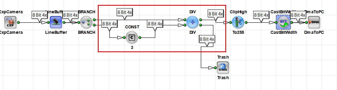
DIV performs integer division. It doesn't preserve fractional digits on its own. For fixed-point division, use the ShiftLeft operator before you divide.
For detailed information about fractional values see the Fixed-Point Arithmetic section of this topic.
Info
DIV uses many FPGA resources. For division by a power of two, use ShiftRight instead.
Handling Arithmetic Overflow with Clip and Cast Operators#
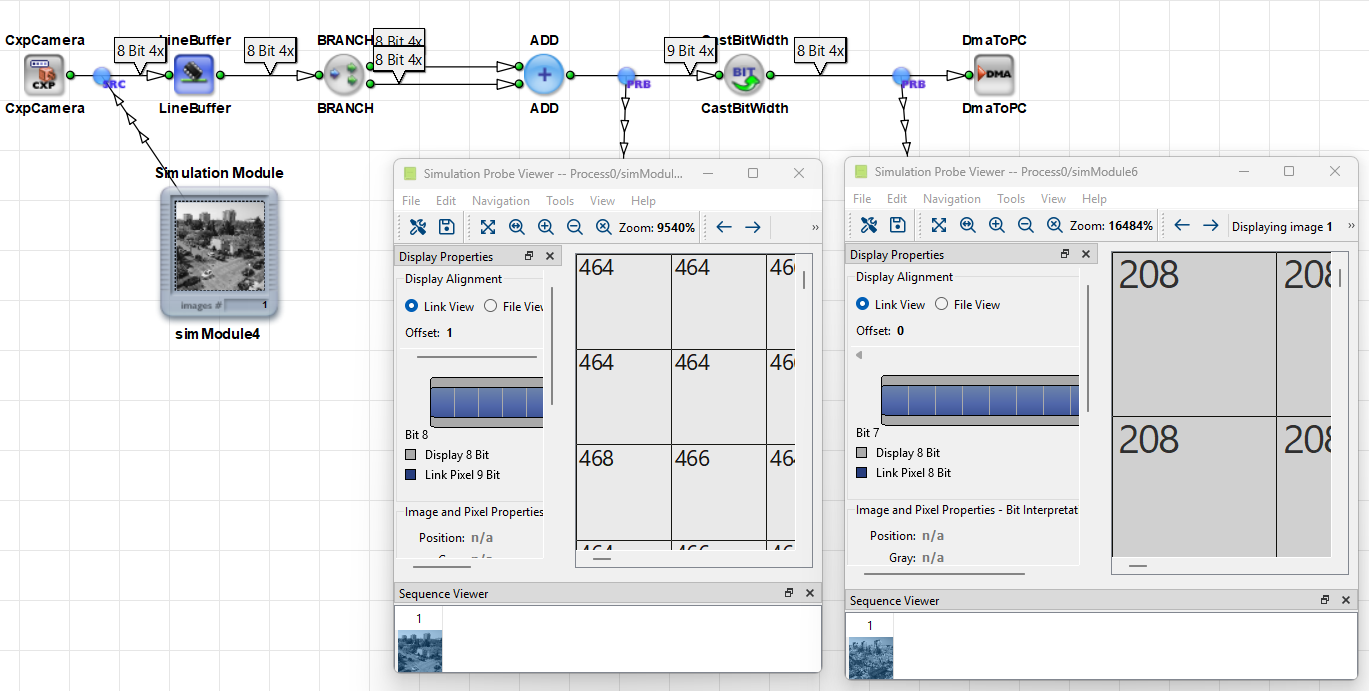
Arithmetic overflow occurs when a result exceeds the range that the current bit width can represent. On an 8-bit unsigned link, the range is 0 to 255. The sum 200 + 100 equals 300. Without enough output bits, the stored value is wrong. The overflow is visible as incorrect pixel values:
Arithmetic overflow should not be confused with the overflow condition handled by the Overflow operator in the Synchronization library: The Overflow operator is used for flow control with non-stoppable sources. For further information about the Overflow operator, see Stoppable and Non-Stoppable Data Streams Tutorial topic.
You can fix an arithmetic overflow with the following operators:
ClipHigh and ClipLow#
The ClipHigh operator limits values to a configurable maximum. Any input value that exceeds the maximum is replaced by the maximum value. The ClipLow operator works similarly for a configurable minimum.
Use ClipHigh and ClipLow to keep values within a target range before reducing the bit width. Configure the clip limits using the module parameters. The valid range depends on the Bit Width input link property and on whether the input link uses signed or unsigned arithmetic.
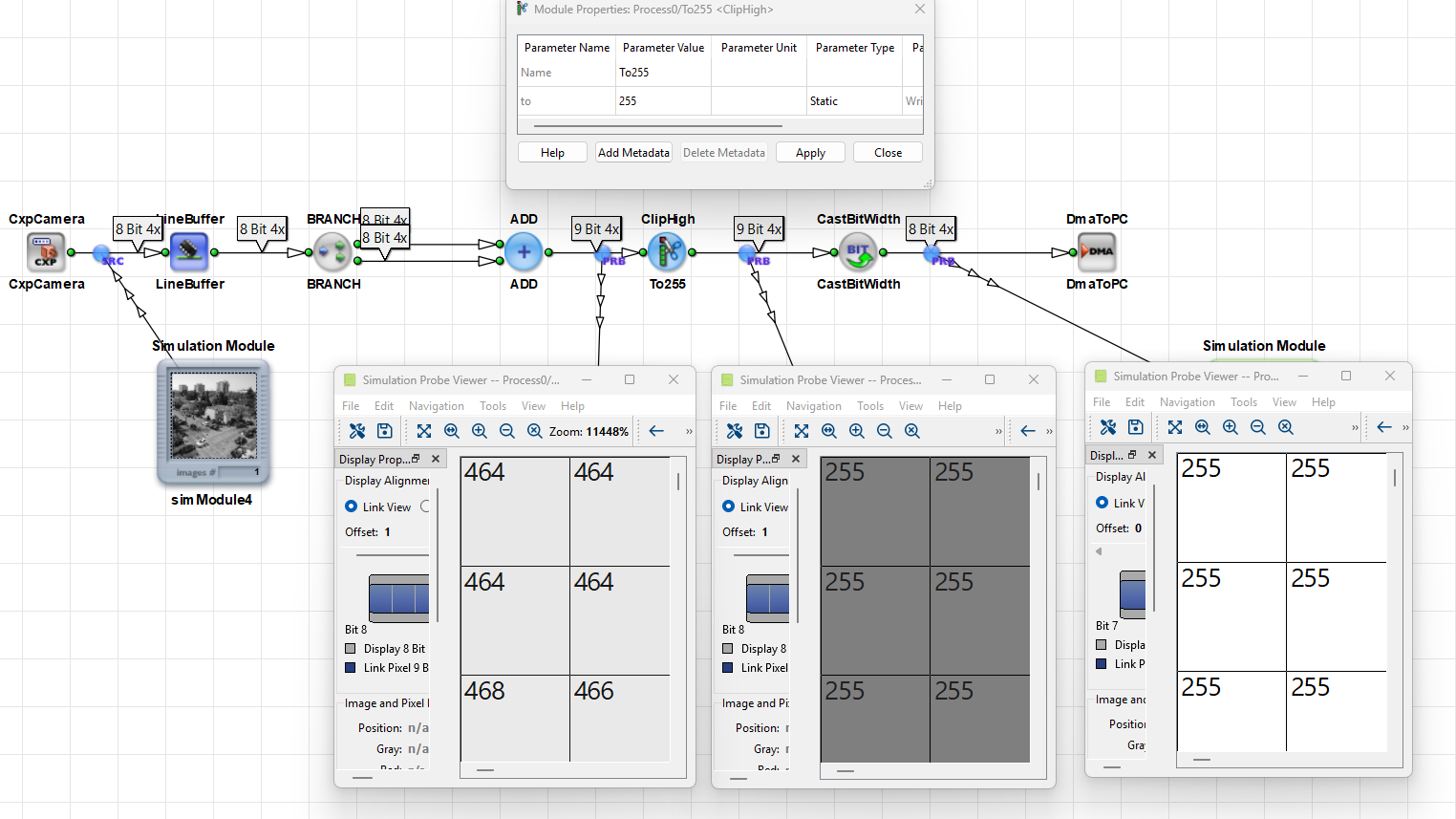
The screenshot shows that ClipHigh sets all pixel values greater than 255 to 255:
CastBitWidth#
The CastBitWidth operator changes the link bit width. You set the link property Bit Width on the output link of the operator.
When the output bit width is greater than the input bit width, the operator keeps the value and adds bits at the most significant positions. For signed values, CastBitWidth performs sign extension.
When the output bit width is less than the input bit width, CastBitWidth discards the most significant bits. As a result, values that cannot be represented within the output bit width are modified. Because this operation removes bits permanently, information required for later processing may be lost.
When reducing the link bit width, Basler recommends the following steps in this order:
- Insert
ClipHighandClipLowto limit the bit width values to the target range. - Insert
CastBitWidthto reduce the bit width.
See also Parameterization Tutorial topic.
Example: Add Pixels and Narrow the Result#
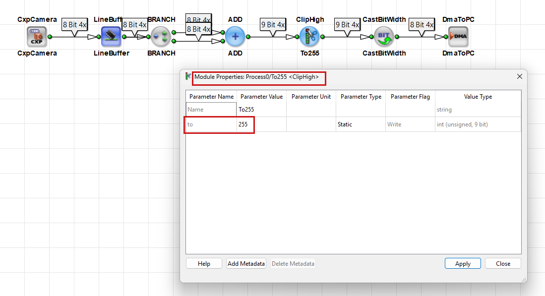
This example adds two 8-bit unsigned pixel streams and returns an 8-bit result for downstream processing:
- Connect two 8-bit image paths to an
ADDoperator. - Check the output link.
ADDproduces a 9-bit result. - Insert
ClipHighafterADD. Set the maximum to 255. - Insert
CastBitWidthafterClipHigh. Set the outputBit Widthto 8. - Run Design Rules Check Level 1 and confirm that all links are valid.
Without ClipHigh, CastBitWidth would only discard the ninth bit and therefore large sums produce wrong pixel values.
Signed and Unsigned Values#
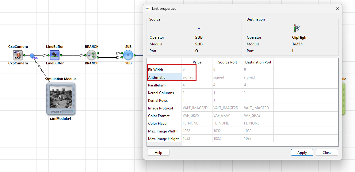
The link property Arithmetic defines whether the generated FPGA pipeline treats values as Signed or Unsigned. For Signed, the hardware uses two's complement representation. You set this property in VisualApplets during design time.
The sign bit is part of the configured bit width.
Changing the Arithmetic Link Property with the CastType Operator#
The CastType operator changes the Arithmetic link property on the output link. The bit pattern stays the same. The generated FPGA logic doesn't change the stored bit pattern, so the operator uses no FPGA resources.
The same bit pattern can represent different decimal values depending on the arithmetic setting. The value 1010 on a 4-bit unsigned link equals 10. The same pattern on a 4-bit signed link equals −6.
Use the CastType operator when downstream operators require a different arithmetic type and the value range still fits.
Checking Whether a Value Fits to a Bit Range#
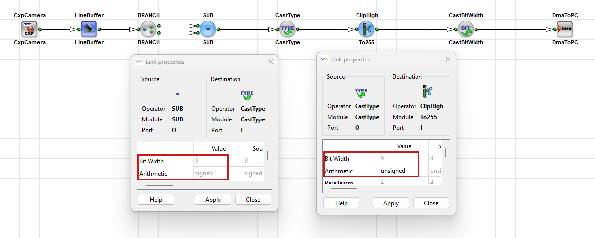
In VisualApplets, parameter values (for example, module parameters of the CONST operator) are entered and displayed as decimal numbers. However, the links connected to an operator can only store values within a specific bit range. Therefore, make sure that the parameter value fits into the bit width of the connected link.
Unsigned Links
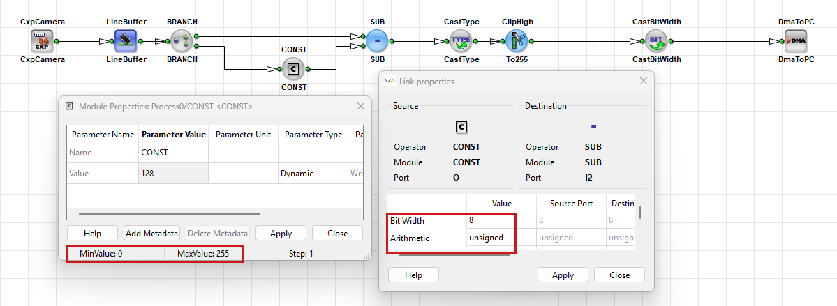
An n-bit unsigned link can represent only positive values and zero. The valid range is:
0 to 2^n − 1
For example, an 8-bit unsigned link can store values from 0 to 255:
On links with ImageProtocol = VALT_SIGNAL, the arithmetic is always Unsigned.
Signed Links
An n-bit signed link can represent both positive and negative values. The valid range is:
−2^(n-1) to 2^(n-1) − 1
For example, an 8-bit signed link can store values from −128 to 127.
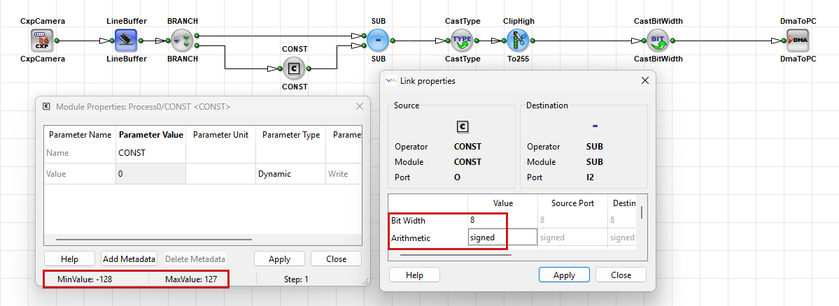
The most significant bit is used as the sign bit and indicates whether the value is positive or negative.
Fixed-Point Arithmetic#
VisualApplets is used to create image-processing designs that are implemented on an FPGA. Unlike software running on a PC, FPGA hardware usually doesn't work with floating-point numbers (such as 0.5 or 1.25). Instead, calculations are typically performed using integers.
To represent fractional values while still using integer arithmetic, VisualApplets uses fixed-point representation. This allows values such as scaling factors, gains, or subpixel coordinates to be stored and processed efficiently in hardware.
This section explains:
- Why fixed-point representation is needed.
- How fractional values are stored in integer bit patterns.
- How Q format defines the position of the decimal point.
- How bit width affects the available value range and precision.
- How operator selection influences the accuracy of calculations.
Every value transmitted on a link is stored as a sequence of bits. Hardware interprets these bits as an integer value.
For example, the bit pattern below represents the integer value 5:
00000101 = 5
However, image-processing applications often require fractional values such as: 0.5, 1.25, or 12.75.
Because the FPGA does not store floating-point numbers, these values are represented using a fixed-point format. In fixed-point representation, the bit pattern is still stored as an integer, but you define a fixed position for the decimal point.
The stored integer value is still 5, but it is interpreted as:
5 / 2^2 = 1.25
because two bits are reserved for the fractional part.
You can think of this as a virtual decimal point that is fixed at a predefined position. In binary arithmetic this split is a binary point, between the bit weights 2^0 and 2^-1. This tutorial keeps the familiar term virtual decimal point. The FPGA performs all calculations using integers, while you interpret the result according to the selected fixed-point format.
Q Format and Bit Allocation#
Fixed-point numbers represent fractional values by assigning some bits to the integer part and some bits to the fractional part. The position of the virtual decimal point is described using Q format.
A Q format is written as:
Qm.n
where:
mis the number of integer bitsnis the number of fractional bits
For signed values, the sign bit is included in the integer part.
For example:
Q4.4
means:
- 4 bits for the integer part
- 4 bits for the fractional part
- 8 bits in total
The number of fractional bits determines the precision of the represented value.
The smallest representable step size is:
1 / 2^n
where n is the number of fractional bits.
Examples:
| Format | Fractional Bits | Smallest Step Size |
|---|---|---|
| Q6.2 | 2 | 0.25 |
| Q4.4 | 4 | 0.0625 |
| Q2.6 | 6 | 0.015625 |
More fractional bits allow smaller differences between adjacent values and therefore higher precision.
The total bit width is fixed. As a result, bits used for the fractional part are no longer available for the integer part.
Therefore:
- More fractional bits provide higher precision but reduce the available integer range.
- Fewer fractional bits provide a larger integer range but lower precision.
When selecting a Q format, balance the required value range against the required precision.
In a fixed-point number, each bit represents a power of two.
Bits to the left of the virtual decimal point represent whole numbers:
..., 2^3, 2^2, 2^1, 2^0
Bits to the right represent fractions:
2^-1, 2^-2, 2^-3, ...
For example, in a Q4.4 format:
Bit position:  7   6   5   4   3    2     1      0
Weight:      2^3  2^2  2^1  2^0  2^-1  2^-2  2^-3  2^-4
The location of the 2^0 bit defines the position of the virtual decimal point. This position is not stored in the hardware; it is defined by the selected Q format and must be interpreted consistently throughout the design.
Example: Q4.4#
In a Q4.4 format, 4 bits are used for the integer part and 4 bits for the fractional part.
The bit pattern
0 0 0 0 . 1 0 0 0
contains a 1 in the first fractional position. This position represents the value 2^-1, which equals 0.5.
Therefore, the bit pattern represents:
0 * 2^0 + 1 * 2^-1 + 0 * 2^-2 + 0 * 2^-3 + 0 * 2^-4 = 0.5
Although the represented value is 0.5, the FPGA stores only the corresponding integer value:
Stored integer value: 8
Represented real value: 0.5
This works because Q4.4 uses 4 fractional bits. The stored integer value is interpreted as:
Real value = Stored integer / 2^4
           = 8 / 16
           = 0.5
Let F be the number of fractional bits.
To convert a real value into its fixed-point representation:
FixedPoint = round(RealValue * 2^F)
Example:
FixedPoint = round(0.5 * 2^4)
           = round(8)
           = 8
Resulting bit pattern:
0000.1000
To convert a fixed-point value back into a real value:
RealValue = FixedPoint / 2^F
Example:
RealValue = 8 / 2^4
          = 8 / 16
          = 0.5
Operators and Design Rules#
Operators process integer bit patterns only. In fixed-point arithmetic, the position of the virtual decimal point is determined by the Q format and must be tracked throughout the design.
The following operators are commonly used to adjust scaling and maintain the intended Q format:
- The
ShiftLeftandShiftRightoperators shift the input bit pattern left or right by a configurable number of bits. A left shift multiplies the value by 2^Shift; a right shift divides it by 2^Shift. These operators are often used after arithmetic operations to restore the desired Q format. SCALEorShiftLeft: Use these operators instead ofMULTwhen multiplying a value by a constant power of two. They perform the same scaling operation, but typically require fewer FPGA resources.- The
MULToperator multiplies two input values. The output bit width equals the sum of the input bit widths. In fixed-point arithmetic, the number of fractional bits in the result is also the sum of the fractional bits of both operands.
Example#
Multiplying a Q4.4 value by another Q4.4 value produces a Q8.8 result:
Q4.4 * Q4.4 -> Q8.8
The result provides higher precision, but it may require a subsequent ShiftRight operation or a bit-width reduction if the design expects a Q4.4 value.
Some operators assume a specific fixed-point format. For example, trigonometric operators such as SIN, COS, TAN, and their inverse functions expect a predefined number of fractional bits for their inputs and outputs.
Before connecting links to such operators, verify the required format in the Arithmetics Library in the Operator Reference.
Design Guideline
Document the Q format at each stage. After multiplication or division, use ShiftRight or bit-width adjustment if needed to restore the intended format.
Displaying Fixed-Point Values in Simulation#
You can use the simulation function in VisualApplets to verify that fixed-point values are interpreted, scaled, and propagated through the design as intended before building the applet. In the Simulation Probe Viewer, link values remain integers, but you can display them as fixed-point by setting fractional bits, choosing signed/unsigned decimal, and optionally applying a scaling factor. This affects display only, not hardware. To check the fixed-point values via simulation in VisualApplets:
- Add a Simulation Source to start of the processing pipeline.
- Add a Simulation Probe to the operator's output link.
- Start simulation via Analysis → Start Simulation.
- Open the Simulation Probe Viewer for the probe you added in step 2.
- In the Simulation Probe Viewer, select signed or unsigned decimal display.
- Set the number of fractional bits to match your Q-format.
- Optionally set a scaling factor for unit conversion, e.g. radians to degrees.
As a result, you see how the Simulation Probes take the fractional bits into account:
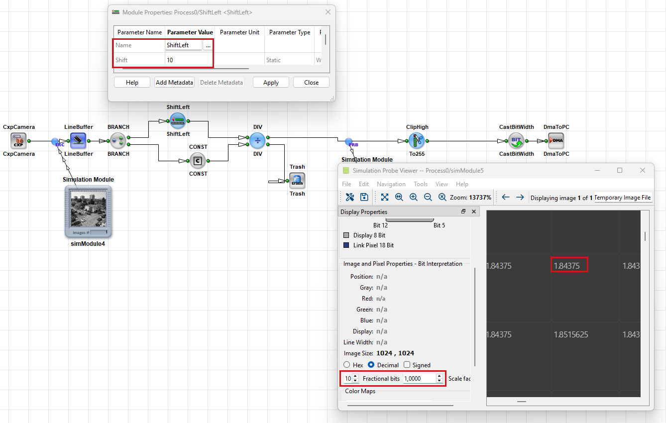
For further information about simulation in VisualApplets, see Simulation in the User Manual.
Extracting Bit Fields with SelectBitField#
The SelectBitField operator extracts a contiguous range of bits from the input value and copies it to the output. Use this operator when you need only a specific portion of a wider data word.
Configure the operator as follows:
- Set the output
Bit Widthon the output link. This determines how many bits are extracted. - Set the
BitOffsetparameter. This specifies the position of the least significant bit (LSB) of the selected field to be copied to the output. The selected bit becomes bit 0 (the least significant bit) of the output value.
For gray images, BitOffset must be in the range:
0 ... Input Bit Width - Output Bit Width
If the input uses signed arithmetic, the extracted bits are always output as an unsigned value.
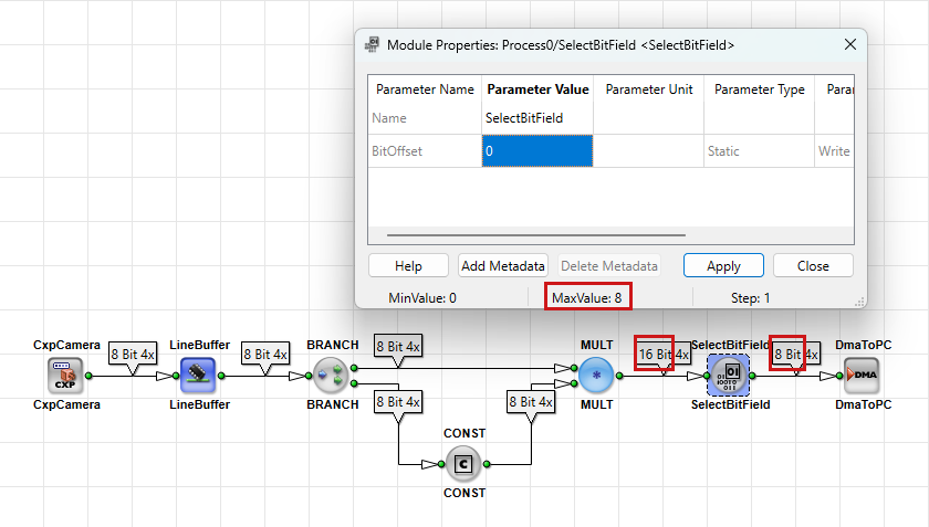
Widening Bit Width for Downstream Software#
Many cameras produce pixel data with bit widths such as 10 or 12 bits per pixel. However, image-processing software and image file formats often work with standard data widths such as 8, 16, or 32 bits.
Therefore, it is common to convert camera data to 16-bit pixels before transferring it to the host PC. You can do this in the following ways:
Using ConvertPixelFormat#
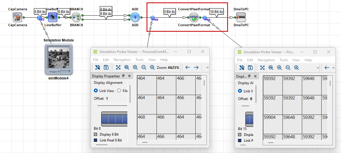
To widen the bit width, you can insert a ConvertPixelFormat operator between the image source or buffer and DmaToPC.
After inserting the ConvertPixelFormat operator, open the output link properties and set Bit Width to 16.
For example, when converting 9-bit pixel data to 16 bits, the operator shifts each pixel value 7 bits to the left and inserts zeros into the newly created least significant bit positions. This preserves the relative brightness range while adapting the data to a 16-bit format.
Using ShiftLeft#
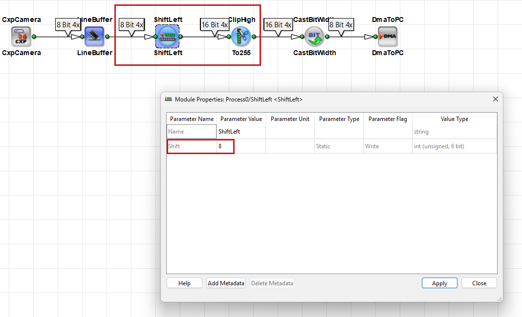
As an alternative, you can also insert a ShiftLeft operator and set the Shift parameter to 7.
A left shift by 7 bits produces the same scaling effect as converting a 9-bit value to a 16-bit value:
9-bit value << 7
The output link then carries 16-bit pixel values.
Using CastBitWidth#
If you want to increase the bit width without changing the numerical value, insert a CastBitWidth operator. Choose this option if downstream software requires a wider bit width, but no scaling of the pixel values is desired.
To change the bit width with a CastBitWidth operator, change the bit width on the output link of the CastBitWidth operator:
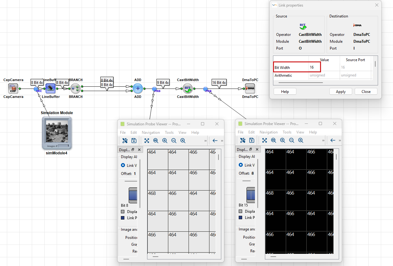
Unlike ConvertPixelFormat or ShiftLeft, CastBitWidth doesn't shift the pixel data. Instead, it adds additional high-order bits while preserving the original value.
Verifying Your Design with DRC#
After you change bit widths or insert arithmetic operators, run Analysis → Design Rules Check Level 1. Level 1 reports bit width mismatches and parameter conflicts in the DRC log. Affected modules and links are highlighted in the design pane.
Run Design Rules Check Level 2 before you build. Level 2 estimates FPGA resource usage. Wide intermediate results and operators such as MULT and DIV increase resource consumption.
Read the DRC log together with highlighted modules and links. For the full workflow, see From Empty Design to Running Applet Tutorial topic.
Key Terms
Basler recommends these practices when you work with bit widths:
- Check the propagated
Bit Widthon downstream links after every arithmetic operator. - Clip values before you cast to a narrower width.
- Plan bit width changes for host software early, for example 16 bits per pixel before the DMA.
- Use
ShiftLeftandShiftRightfor power-of-two scaling instead ofMULTandDIVwhen possible. - Consult the Operator Reference when a parameter value doesn't stick.
Related Topics#
- Parameterization Tutorial topic —
BitWidthand arithmetic link properties - Rules of Links in the User Manual — formal link rules
- From Empty Design to Running Applet Tutorial topic — DRC, simulation, and build
- VisualApplets Fundamentals Tutorial topic — pipeline and FPGA resources
- Operator Reference — supported link formats
- CastBitWidth in the Operator Reference
- ClipHigh in the Operator Reference
- ClipLow in the Operator Reference
- ConvertPixelFormat in the Operator Reference
- SelectBitField in the Operator Reference
- ShiftLeft in the Operator Reference
- ShiftRight in the Operator Reference