From Empty Design to Running Applet#
Key Terms
You can follow this learning path without frame grabber hardware on your desk. You run design, parameter setup, design rule checks, and simulation in VisualApplets on the PC. Build needs the FPGA toolchain (typically Xilinx Vivado) on the PC; it does not need the board. Flash/load and runtime verification need the frame grabber and runtime software, for example the Basler Framegrabber SDK. For full integration tests you also need the frame grabber and a camera or another image source.
For a step-by-step walkthrough of the same workflow, see Hardware Applet: From Idea to Application in the User Manual.
For a short introduction to designing, building, and using an applet in microDisplay X, see Getting Started in the User Manual.
Workflow Overview#
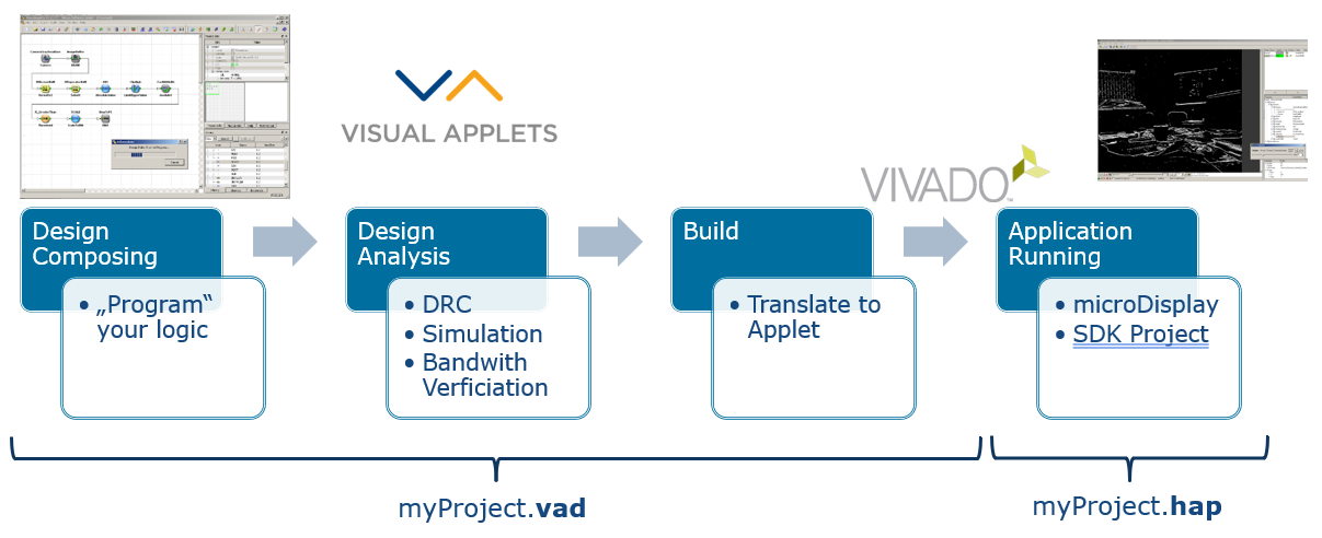
The overall workflow from a VisualApplets design to a running applet is as follows.
In VisualApplets on the PC:
- Design the applet. Place operators as modules in the design panel and add links between them. Set module and link properties.
- Run DRC Level 1 and 2 to check formal correctness and estimate FPGA resources before you build. DRC Levels 1 and 2 also run automatically when you start simulation or build.
- Simulate the design with test images. Simulation starts only if DRC Level 1 reports no errors.
- Build the hardware applet and produce the *.hap file. The build uses the FPGA toolchain on the PC. It does not require the frame grabber to be connected.
On the frame grabber and host:
- For microEnable 5 family platforms, flash the applet to the board. For microEnable 6 / imaFlex boards, load the applet to the hardware.
- Use the applet on the hardware with microDisplay X, the Framegrabber SDK, or pylon.
This tutorial refers mainly to microEnable 5 (mE5) and imaFlex frame grabbers (CXP-12 Quad/Penta, microEnable 6 family). The operator libraries differ by platform. For example, mE5 designs use ImageBuffer for DRAM line buffering, while imaFlex designs use LineBuffer.
Key Terms
A hardware applet is the *.hap file that the build produces and the frame grabber runs. Design time is when you edit the *.vad project in VisualApplets on the PC. Runtime is when host software loads the applet to the frame grabber FPGA and acquires images. Simulation in VisualApplets is not runtime.
Starting a New Project#
You carry out the design phase entirely in VisualApplets. Start the application from VisualApplets.exe in the bin folder of the installation directory, from the Windows Start menu, or from a desktop shortcut if you created one.
When no project is loaded, the main window shows an empty workspace. To start a project, click File and New, or press Ctrl + n. In the New Project dialog, you set the project name, the target hardware platform such as microEnable 5 marathon VCL, and the target runtime such as Win 64.
Info
You can change these project settings later, but the platform determines which operator libraries and build options apply, so switching platforms may require you to replace or reparameterize some modules.
After you confirm with OK, VisualApplets opens a blank design window. A new design always contains two fixed modules called AppletProperties and BoardStatus. AppletProperties is used to set general properties of the design, such as author and version; AppletProperties also provides access to interface properties for certain hardware platforms. BoardStatus is used at runtime to provide properties such as PCIe interface status and temperature. The Project Info tab summarizes the current project name, hardware target, and platform information.
Operators, Modules, Links, and the Pipeline#
You design the image-processing pipeline in VisualApplets from operators that live in the Operator Library in the design window. Drag operators into the diagram to place them. Each placed instance is a module. Modules expose input and output ports. Connect an output port of one module to an input port of another to create a link. The diagram shows each link as an arrow. Together, modules and links describe the image-processing pipeline that the build implements on the FPGA. Processing order follows the connection order.
Operators and links both have properties such as dimensions, bit width, protocol, parallelism, and other settings. Links carry their own properties along the connection. Which link fields you may edit depends on the upstream operator. Non-editable link fields receive their values either from the upstream operator or from the link's position in the chain. Additionally, rules also automatically propagate properties through the pipeline. For example, you set some properties only on the camera output link. They propagate downstream until an operator changes them. Double-click a link or module to open and change its properties. The in-product help and the Operator Reference document operator-specific behavior.
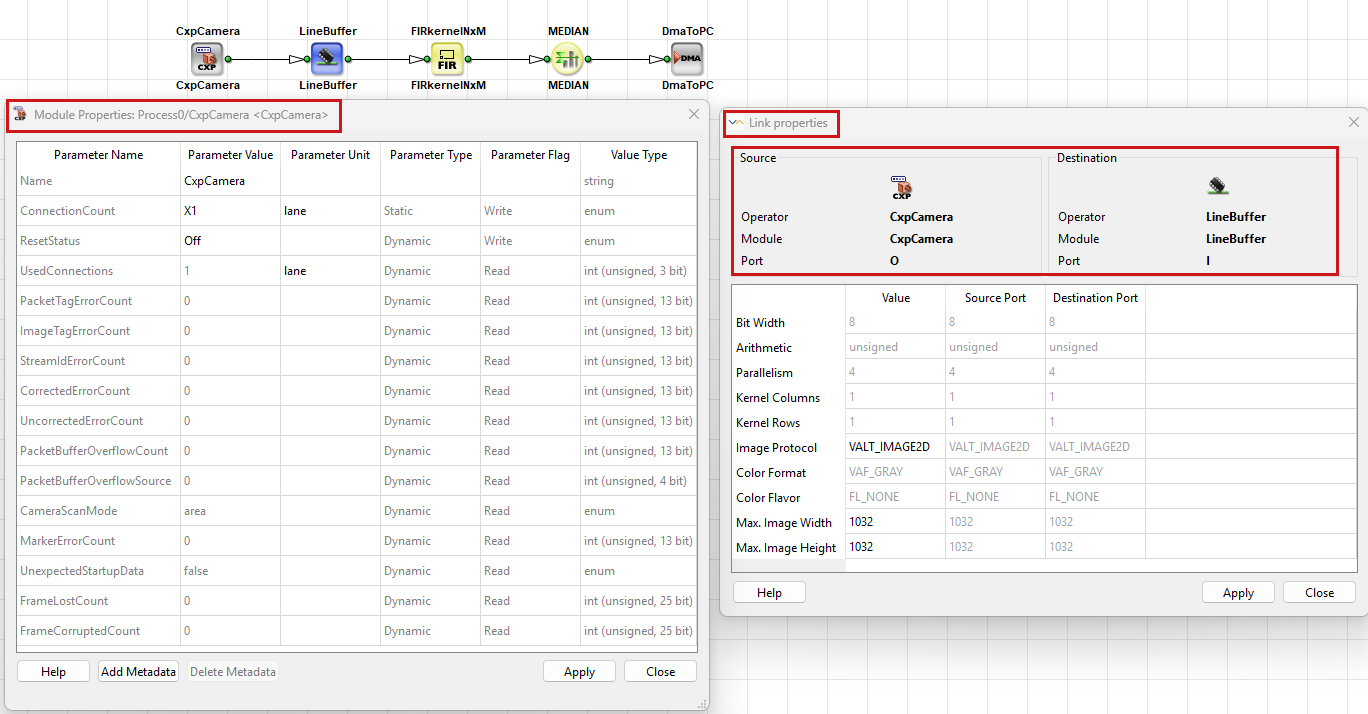
Basler recommends that you save the design regularly, rename modules when that improves readability, and use HierarchicalBox elements to structure larger designs. You can start from example designs under Examples in the installation directory. See Processing Examples in the User Manual for pointers.
Setting Parameters at Design Time#
Link properties describe how image data travels along a connection. They cover settings such as maximum image size, image protocol, bit width, and parallelism. Higher maximum dimensions and higher parallelism typically use more FPGA resources, so Basler recommends that you set these values only as high as your application needs. You edit link properties only in VisualApplets, not at runtime. For a detailed description of link properties, see Parameterization Tutorial topic.
Module parameters are either static or dynamic. You change static parameters only in VisualApplets during design time. You can set dynamic parameters in VisualApplets as defaults, and you can change them later from host software while the applet runs on the frame grabber.
Design Rules Check (DRC)#
After you create the design and set parameters, Basler recommends that you run Design Rules Check Level 1 and Design Rules Check Level 2. Select Analysis → Design Rules Check Level 1, or Design Rules Check Level 2, or the matching icons on the build toolbar.
- Starting Level 2 automatically runs Level 1 first.
- Level 1 also runs automatically before simulation and build. See Design Rules Check in the User Manual for details.
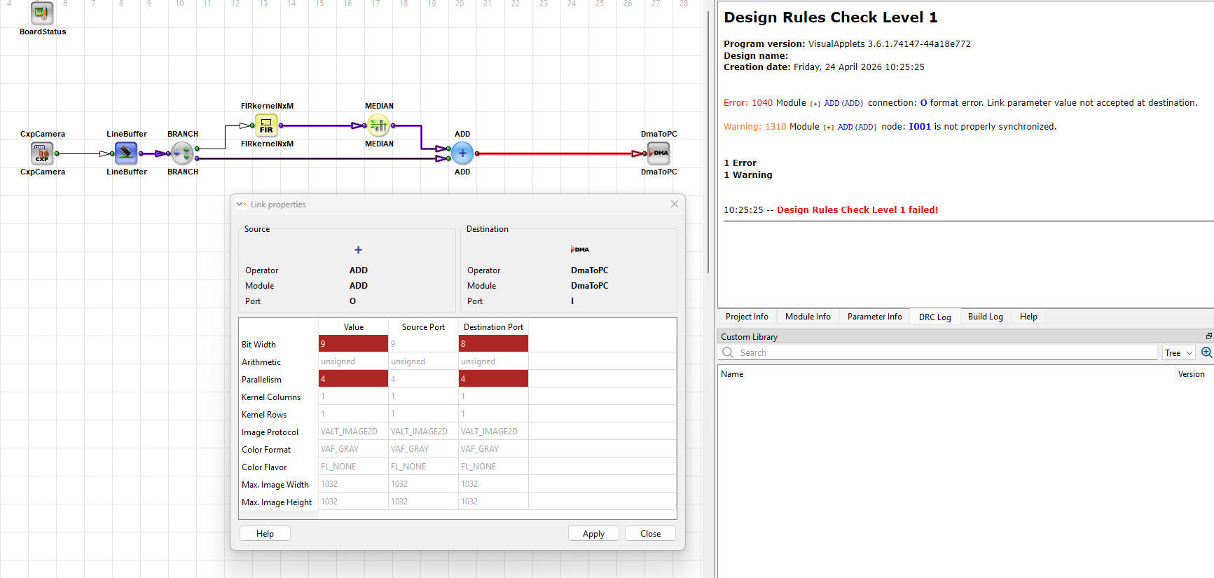
DRC Level 1 reports formal design problems in the DRC log and highlights affected locations in the design pane. Typical issues include mismatching bit widths on links, and ROI or image size inconsistencies. You must clear Level 1 errors before you build the hardware applet.
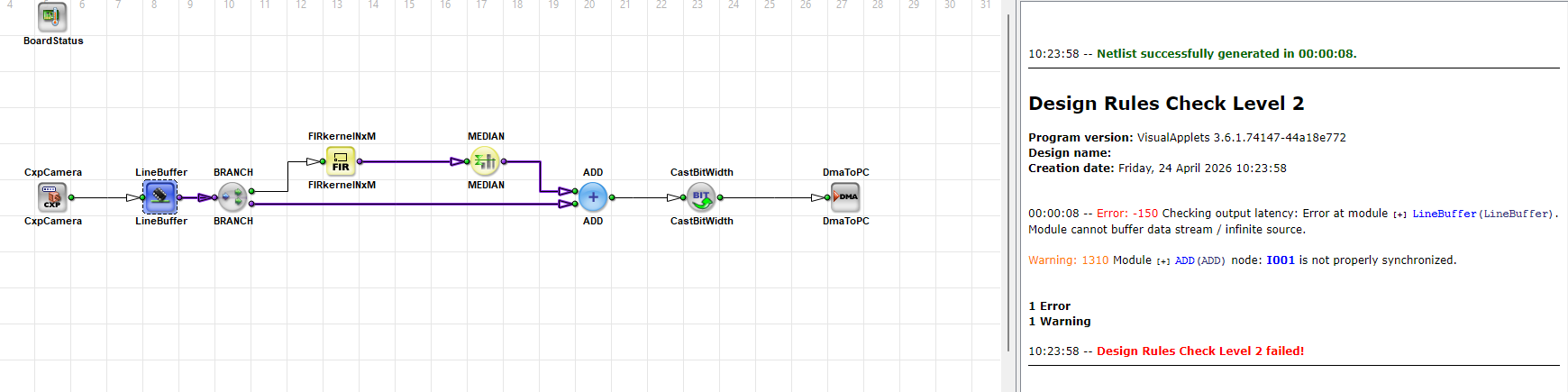
DRC Level 2 runs further checks and estimates FPGA resource usage. Treat this estimate as a guideline, not an exact prediction: For some operators, later logic optimization during build can change the final resource usage, so even an estimation above 100% can still result in a successful build in some cases. If any resource is far above 100%, simplify the design, reduce parallelism or image dimensions, or choose other operators, then run the checks again.
The figure below shows a typical DRC log after Design Rules Check Level 1 and 2 without errors: formal status plus estimated use of LUTs, flip-flops, block RAM, and arithmetic resources.
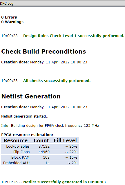
To see which module uses how many resources, open Analysis → View FPGA Resources. The FPGA Resource Estimation dialog displays both an estimated breakdown for the entire design and for each module. You can export the table as CSV. To see only the FPGA resources of a selected module, open the context menu of this module and select FPGA Resources. See also FPGA Resource Estimation in the User Manual.
If the DRC log reports problems, use the DRC messages together with highlighted modules or links to fix the errors. For more detail, see Design Rules Check in the User Manual.
Link Colors#
In the design pane, red link highlighting marks formal design errors on the image path. In Link Properties or Module Properties dialogs, red-marked links can also provide tooltip messages with details about the specific error type.
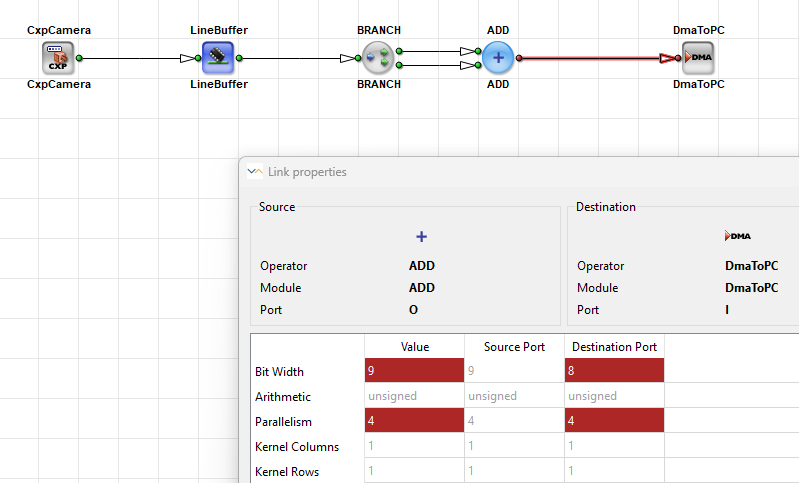
Purple highlighting marks violations of synchronization rules between branches, such as O-type network rules. You must fix red errors and purple synchronization violations before you deploy the applet to hardware. For processing with signals (i.e., links using Image Protocol = VALT_SIGNAL), purple links are permitted.
These colors are not a traffic-light status for the whole design. Green links, shown after you apply a property change, mean that VisualApplets has propagated and validated the updated link properties. Green does not by itself mean that the design is ready to build. See Propagation of Link Properties Tutorial topic.
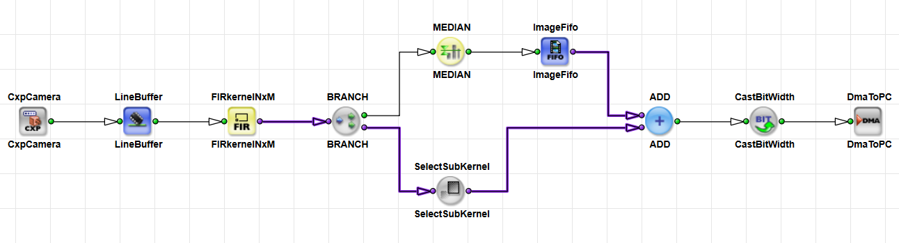
For more details on link rules, see Rules of Links in the User Manual and Operator Types and Synchronization Tutorial topic.
Simulation vs. DRC#
You can't start simulation if DRC Level 1 reports an error. Warnings, including synchronization warnings, don't block simulation. Red states indicate errors and stop simulation. Purple states mark synchronization problems. You may still simulate in that case, but you should fix them before you rely on the applet on hardware.
Even when DRC Level 1 and 2 complete without errors, simulation can still fail. For example, simulation fails when the loaded image width isn't an integer multiple of the link parallelism, or when the image exceeds maximum image dimensions set on the links. To fix these issues, align the simulation image size with those constraints or adjust the link properties.
The following image shows an error in DRC Level 1:
The following image shows an error in DRC Level 2:
Simulation#
During design, simulation feeds test images through the pipeline and lets you inspect intermediate results without hardware. Add simulation sources to inject images and simulation probes to view data on specific links. VisualApplets ships test images under %VASINSTALLDIR%/testimages. You can also load your own images into simulation sources. TIFF is the preferred format, but VisualApplets supports loading images in many other common formats as well.
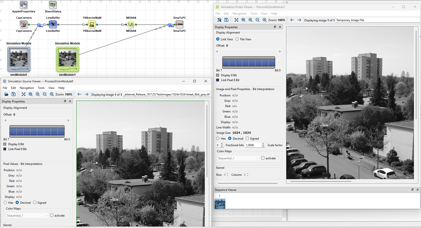
When you start simulation from Analysis → Start Simulation or from the toolbar control, VisualApplets automatically runs DRC Level 1. The Simulation window lists active sources and probes and shows the DRC Level 1 outcome in the lower pane. You don't need DRC Level 2 to simulate, but Basler recommends that you run DRC Level 2 before you build the applet so you get the FPGA resource estimate. See Simulation in the User Manual for all further simulation options, modes, and windows.
You can run multiple simulation cycles in one simulation session: In the Simulation window, set Processing cycles and click Start. If the simulation source contains only one image, VisualApplets reuses that image for every cycle. If the source contains several images, each new cycle uses the next image in order. After the last image, the sequence starts again from the first.
For the pixel values on image data paths, simulation usually matches hardware for the data under test. In a Simulation Probe, you inspect pixels in detail by zooming. Tools such as image histograms can help you with interpreting the pixel data.
Simulation does not show all hardware effects. Deadlocks, undersized buffers, shared DRAM bandwidth limits, and some overflow cases often appear only on the frame grabber. A successful simulation is not a substitute for a runtime test on hardware.
Building the Hardware Applet#
When you build your design, VisualApplets translates the design into an FPGA bitstream and packages it together with content for the runtime software interface into a file called hardware applet. The build needs a supported AMD/Xilinx toolchain installed and configured on the build computer. Use Vivado according to your platform and VisualApplets version. See Installing VisualApplets for an overview of which toolchain versions match which frame grabber platform. For detailed instructions on building your hardware applet, see Build in the User Manual.
Build duration depends on FPGA logic usage, the hardware target platform, and the complexity of the design. Simple examples may finish in minutes, while large designs can take hours. When the build succeeds, the output *.hap file typically uses the same base name as the design file. For example, Sobel_Filter.vad yields Sobel_Filter.hap.
Flashing, Runtime Loading, and Host Software#
For microEnable 5 family boards you must flash the new applet with microDiagnostics so the firmware partition on the board contains your *.hap file. For microEnable 6 boards, you load the applet to your hardware. For instructions on how to flash or load your applet to your frame grabber with the microDiagnostics tool of the Framegrabber SDK, see Managing Applets in microDiagnostics.
To work with the built hardware applet, open the applet in microDisplay X. The parameter tree in microDisplay X reflects module names from the design, so choose clear module names in VisualApplets. Dynamic parameters appear there. You can change some parameters during acquisition, but others must be set before acquisition starts. DMA dimensions are a typical case. You can change other parameters during acquisition, such as a threshold value.
For microDisplay X features and acquisition behavior, see microDisplay X in the Framegrabber SDK documentation.
Alternatively, integrate acquisition and parameter control in your own application with the Framegrabber API. VisualApplets can generate example C++ projects with Build and Generate SDK Example. Those projects contain initialization, memory allocation, Fg_setParameterWithType / Fg_getParameterWithType calls, acquisition start and stop, and cleanup. See Framegrabber SDK in the User Manual for how to generate an SDK Example.
Treat the generated code as a starting point. Find the API reference in the Framegrabber SDK documentation, for example basler_fg.h and the Framegrabber API introduction.
Design Time and Runtime#
At design time, you edit the graphical pipeline, set static and dynamic parameters, define link properties, run DRC Level 1 and 2, and simulate. Every time you start simulation, VisualApplets runs DRC Level 1 automatically. You also generate the build output as a *.hap file.
At runtime, host software loads that applet, configures dynamic parameters, and starts acquisition. The module names and hierarchy defined in the VisualApplets design are also used in the parameter tree and API. Consistent naming and documentation help integrators and simplify field tuning.
Related Topics#
- VisualApplets Fundamentals Tutorial topic — design, build, and hardware applet
- Parameterization Tutorial topic — link properties and module parameters at design time
- Pipeline Concept Tutorial topic — modules, links, and pipeline structure
- Operator Types and Synchronization Tutorial topic — operator types and link colors
- Design Rules Check in the User Manual — DRC Level 1 and Level 2
- Simulation in the User Manual — simulation sources, probes, and modes
- Build in the User Manual — generating the hardware applet
- Installing VisualApplets — Xilinx toolchain versions