Latency#
Key Terms
Latency is the time a single pixel needs to pass through the generated FPGA pipeline from camera (or other source) input to an output such as DmaToPC. That delay happens on the frame grabber, not in the VisualApplets editor. Bandwidth is how many pixels per second can flow through a link.
A design can have high bandwidth and low latency at the same time: many pixels move in parallel through the FPGA pipeline, but the first pixel of a frame still needs some time before it is handed to DMA.
Latency vs. Bandwidth#
Bandwidth and latency describe different properties of the same pipeline:
| Bandwidth | Latency | |
|---|---|---|
| Question | How much data flows per second? | How long does one pixel wait until it is processed? |
| Depends on | Parallelism and Base Design Clock | Operator type and algorithm |
| Formula (link) | Bandwidth = parallelism × Base Design Clock | Defined per operator; see below |
A pipeline can transfer and process image data at the same time. For example, while pixel 1000 is already at the output, pixel 5000 may still be at the camera input. The overall data rate (bandwidth) stays high because multiple pixels run through the design in parallel. Latency only describes the delay of an individual pixel.
Design Guideline
In the FPGA pipeline generated from a VisualApplets design, latency is kept close to the theoretical minimum. Most operators do not store a full image. They forward results as soon as the information is available.
Latency Definition#
Latency is the delay of a pixel in a design — the time from when a pixel enters the processing chain until it leaves it (for example, until it reaches DmaToPC).
Important points:
- Latency is defined individually by each operator and mostly depends on its algorithmic implementation.
- Adding modules does not reduce throughput. All stages in the generated FPGA pipeline run in parallel: while one module processes a pixel, the other modules process other pixels. After the pipeline has filled, a longer chain can still accept a new pixel (or pixel packet) on every clock cycle.
- Adding operators can increase latency. Each operator may add delay on the path of a single pixel, and those delays add up along the chain. A few clock cycles from O-type operators are typically small compared with the line or frame delay of a buffer.
- Latency is not the same as blocking or buffer fill level. If downstream processing is slow, buffers can fill up and the delay grows further. This topic describes the minimum latency built into the operators themselves.
Example Design#
The following design is used throughout this topic. It shows a simple acquisition path with one buffer and two processing steps:
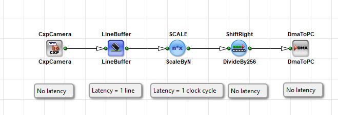
The latency annotations in the design above apply to this specific example:
| Operator | Latency in this example |
|---|---|
CxpCamera | No additional algorithmic latency in this example |
LineBuffer | 1 line |
ScaleByN | 1 clock cycle |
ShiftRight | No additional latency |
DmaToPC | No additional algorithmic latency in this example |
The total latency for a pixel on this path is dominated by the one-line delay of LineBuffer, plus the small processing delays of the other operators. "No additional algorithmic latency" for CxpCamera and DmaToPC means those operators add no extra delay of that kind in this example. It does not mean that the pixel appears immediately on the PC. Camera interface timing, PCIe transfer, host buffering, and display are outside this table.
Pixel Flow in the Example Design#
In the example design, pixels are transferred from the camera through the camera interface into LineBuffer. The LineBuffer collects one full line before it forwards data to the output.
After a full line is stored in LineBuffer, the buffer outputs the pixels of that line. At the same time, the camera already transfers the next line. This is the pipelined behavior of the generated FPGA hardware: acquisition, buffering, processing, and DMA can overlap. VisualApplets describes that pipeline; it does not process the camera stream itself.
Calculating Latency#
Latency depends on the operator. There is no single value for an entire design. You add up (or follow in time) the delays along the path of one pixel.
Line-Based Latency (Buffer Operators)#
Buffer operators such as ImageBuffer and LineBuffer need at least one full line before they can output the first pixel of that line. For LineBuffer in the example above:
Latency = 1 line
Measured in time, the latency of one line is:
Line latency = (pixels per line) / (pixel rate of the link)
The pixel rate depends on parallelism and the Base Design Clock. A wider line or a slower link increases the time until the first pixel leaves the buffer.
Clock-Cycle Latency (Processing Operators)#
Many processing operators delay a pixel by a fixed number of clock cycles. After the pipeline has filled, they can still accept and output one pixel (or one parallel packet of pixels) on every clock cycle. The delay of a single pixel is then only those internal register stages.
In the example design, ScaleByN adds:
Latency = 1 clock cycle
Measured in time, the latency of one clock cycle is:
Cycle latency = 1 / Base Design Clock frequency
For example, at a Base Design Clock of 312.5 MHz, one clock cycle is 3.2 ns.
Operators, such as ShiftRight in this example, add no meaningful latency in practice. They forward results as soon as the input value is available.
Operator Types and Latency#
VisualApplets groups operators into types. The type helps you estimate the latency:
| Type | Icon Shape | Typical Latency Behavior |
|---|---|---|
| O-type | Round | Very small, fixed delay — usually a constant number of clock cycles. Example: a delay of about 3.2 ns (one cycle at 312.5 MHz Base Design Clock). |
| M-type | Square | Variable delay. Can buffer lines or frames, change image dimensions, or block the input. Check the operator documentation for the exact latency. |
| P-type | Square | Similar to M-type, but does not actively block the input. Check the operator documentation for the exact latency. |
CxpCamera, LineBuffer, and DmaToPC are M-type operators. ScaleByN and ShiftRight are O-type operators. Even though DmaToPC is M-type, it does not add a large algorithmic delay in the example — it hands data to DMA as soon as data arrives. The time until the image is visible in host software is a separate, later delay.
Key Terms
Think of O-type operators as short pipe sections with a fixed length. Think of M-type operators as sections that may contain a storage tank (buffer) or more complex machinery. The tank must fill before the first drop comes out — that is line-based latency. Those pipes and tanks are hardware stages on the FPGA, generated from the modules you placed in VisualApplets.
Parallelism and Latency#
Parallelism does not remove latency. It increases bandwidth: More pixels per clock cycle move through the links.
Example: With parallelism 4, four pixels pass through a link in one clock cycle. The first pixel of a frame still needs the same operator delays, for example, one line in ImageBuffer. After the pipeline is full, four new pixels can leave the operator on every clock cycle.
- High parallelism → high throughput (bandwidth).
- Buffer and algorithm → latency of the first pixel.
Both properties are independent. VisualApplets designs aim for high bandwidth and minimum latency in the generated FPGA pipeline.
Finding Latency Values for Operators#
To find the latency values for the operators you want to use in your design, use these sources:
- Operator Reference — Each operator documents its latency (or processing delay) in the Operator Reference.
- In-product help — Select the operator in the design and open the help for parameter and timing details. This is the same content as in the Operator Reference, provided as in-tool help in VisualApplets.
For M-type operators especially, always check the documentation. Latency can depend on parameters (for example, kernel size in filter operators, or buffer depth in memory operators).
Most operators don't store a full image. They calculate output results as soon as the information is available and the output isn't blocked. That is why latency in the generated FPGA pipeline is kept close to the theoretical minimum for the chosen algorithm.
If the output is blocked, for example, because the PC can't accept data fast enough, the buffer fill level increases and the time until a pixel appears at the host increases. That additional delay is not a fixed operator latency — it comes from flow control and buffering under load.
Related Topics#
- Pipeline Concept Tutorial topic — unbuffered flow and concurrent processing
- Parallelism Tutorial topic — parallelism and latency
- Operator Types and Synchronization Tutorial topic — operator types and latency
- Memory Elements Tutorial topic — line latency of buffer operators
- Working with Kernels Tutorial topic — kernel-related delay
- Bandwidth of an Applet in the User Manual — bandwidth versus latency
- Operator Reference — latency values of individual operators
- Device Resources — Base Design Clock frequencies