Parameterization#
Key Terms
A link is the connection between two modules. Link properties describe the data format on that connection, for example bits per pixel or maximum image size. You set them only in VisualApplets during design time. Module parameters are the settings on a module, for example a threshold value or a camera format. If a value that you enter doesn't stick, link properties often limit what the module can accept.
Static parameters can be changed only in VisualApplets on the PC (design time). Dynamic parameters can also be changed at runtime, when host software talks to the applet on the frame grabber. Values you set for dynamic parameters in VisualApplets are the defaults for runtime. Simulation in VisualApplets is not runtime.
Link Properties and Module Parameters#
VisualApplets uses two kinds of settings:
Link properties are set on links and define e.g. maximum image width and height, bit width, parallelism, image protocol, color format, and kernel size. Link properties constrain the operators that are connected to the link. If a module parameter conflicts with link properties, VisualApplets either adjusts the value directly or reports an error. Link properties are always static: You change them only in VisualApplets during the design phase. Link properties propagate through the pipeline and affect all downstream operators until an operator changes them.
Module parameters define operator behavior, for example an operation mode, an image position, or the size of a region of interest. They can be static or dynamic. You change static parameters only during design time. Dynamic parameters can also be changed at runtime from host software. Static parameters typically use fewer FPGA resources than dynamic parameters. Dynamic parameters are useful when you need to switch camera formats or processing settings while the applet runs. Module parameters are often limited by link properties. If you can't set a value and VisualApplets auto-corrects it, check the link properties on the connected links. Many operators also define link properties on their output, so a change on one side of the design can propagate to the other.
Link Properties and Module Parameters of the CxpCamera Operator:
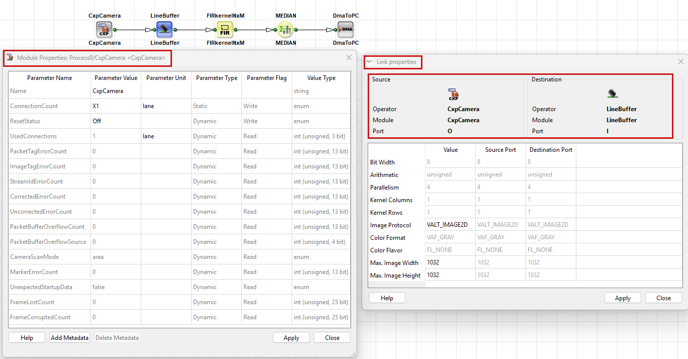
For the formal rules behind links, see Rules of Links in the User Manual. For the editing workflow in the VisualApplets GUI, see Parameterization in the User Manual.
Link Properties#
Each link between modules is defined by its link properties. All links have the same set of properties. Link properties are always static: You change them only in VisualApplets during the design phase. You open the link properties by double-clicking the link or by right-clicking the link and selecting Properties.
The following link properties define how image data is transported on a connection:
-
BitWidth: The number of bits per pixel on the link. For color links, the bit width covers all color components together. Camera operators often set the initial bit width. For links withImageProtocol=VALT_SIGNAL, the bit width is always 1 bit.- Some operators let you set the output
BitWidthdirectly on the link, for exampleCastBitWidth,CONST, orModuloCount. Others derive the outputBitWidthautomatically from input link properties or module parameters. For example,ShiftLeftadds the value of parameterShiftto the input bit width, andMULTuses the sum of the input bit widths. Operators such asCoordinate_XandCoordinate_Ycalculate the outputBitWidthfromMaxImageWidthandMaxImageHeight. For operators with automatic outputBitWidth, the Operator Reference shows auto in the Supported Link Format table, and you usually can't edit the value on the link. When an operator changes the outputBitWidth, VisualApplets propagates the new value to downstream links until another operator changes it again.
- Some operators let you set the output
-
Arithmetic: Defines the arithmetic used for a link. The arithmetic can be eitherSignedorUnsigned.- If set to
Signed, two's complement arithmetic is used. The sign bit is included in the configured bit width. - For the image protocol
VALT_SIGNAL, the arithmetic is alwaysUnsigned, regardless of the configured bit width.
- If set to
-
Parallelism: The number of pixels that are transferred in parallel between two modules within one Base Design Clock cycle. For more information, see Parallelism Tutorial topic. -
KernelColumnsandKernelRows: The number of neighboring pixels per clock cycle that filter operators need. For the image protocolVALT_SIGNAL, both values are always 1. For more information, see Working with Kernels Tutorial topic. -
ImageProtocol: Defines the structure of the data stream on the link. The following image protocols are available:VALT_IMAGE2D: Two-dimensional images with end-of-line and end-of-frame markers, for example from area scan cameras.VALT_LINE1D: One-dimensional line data, for example from line scan cameras.VALT_PIXEL0D: A continuous pixel stream without image dimension information.VALT_SIGNAL: Single-bit signals that are valid at every clock cycle, for example in trigger logic.
The image protocol can change inside a design. For example,
SplitImagecan cut a 1D image stream into 2D images of a defined height. For more information, see Image Protocols, Image Dimensions and Data Structure in the User Manual. -
ColorFormatandColorFlavor: These properties describe how pixel data is represented, for example gray, or RGB. Some operators support only certain color formats. On some platforms, CoaXPress camera operators accept gray formats only. To produce color output, use operators such asMergeComponents. Operators such asMergeComponents,ParallelUp, andCastBitWidthcan change color-related link properties. -
MaxImageWidthandMaxImageHeight: The maximum image dimensions that the link can carry. Images on the link must not exceed these values, but they may be smaller. These properties are relevant for operators that buffer lines or full images, such asImageFifo,LineBuffer, orColMax. Set them at least as large as the largest image in the processing path. Values that are too small cause Design Rules Check (DRC) errors. Larger values use more FPGA resources. Camera operators or operators such asSetDimensionoften set these properties.MaxImageHeighthas no effect whenImageProtocolis set toVALT_LINE1D,VALT_PIXEL0D, orVALT_SIGNAL.
Info
The higher the maximum image dimensions and the parallelism you choose, the more FPGA resources the design consumes. Basler recommends that you set these values only as high as your application requires.
Each operator defines which output link properties it allows and which values are fixed. Some properties on a link are disabled because the upstream operator doesn't permit editing them. The Operator Reference documents the allowed link formats for each operator.
Propagation of Link Properties#
Link properties are defined by operators. You can change some properties directly on the output link of an operator. Others are fixed or are derived from module parameters or from input link properties. When you change a link property, VisualApplets propagates the change through successive modules and links.
After you change a value, click Apply in the properties dialog. If the change is accepted, affected links turn green in the design pane. Green means that VisualApplets has propagated and validated the updated link properties. It is not a traffic-light "all valid" mark for the whole design.
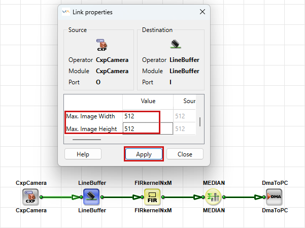
Link properties propagate through modules until an operator changes them. If the downstream link doesn't allow editing a property, the upstream operator or an intermediate operator that can change that property is the place to set it. For example, an ImageBuffer operator doesn't change the link bit width. You must set the bit width on the camera output link or insert an operator such as ConvertPixelFormat or ShiftLeft that changes the bit width.
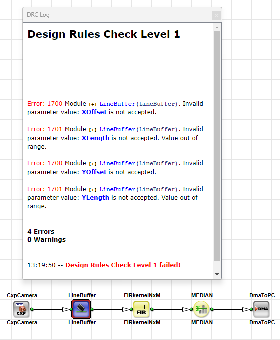
A link property change can also conflict with a module parameter. In that case, VisualApplets marks the module and the affected parameters in red:

Run Design Rules Check Level 1 and read the DRC log to locate the error. Typical causes include a region of interest that exceeds MaxImageWidth or MaxImageHeight, or a parameter value outside the range allowed by the link bit width:
Module Parameters#
Module parameters differ for each operator. They control how the operator processes data. Module parameters can be static or dynamic. You set static parameters only in VisualApplets during design time. Dynamic parameters can also be changed at runtime from host software through microDisplay X, the Framegrabber SDK, or pylon. In the Module Properties dialog, the Parameter Type column shows whether a parameter is static or dynamic:
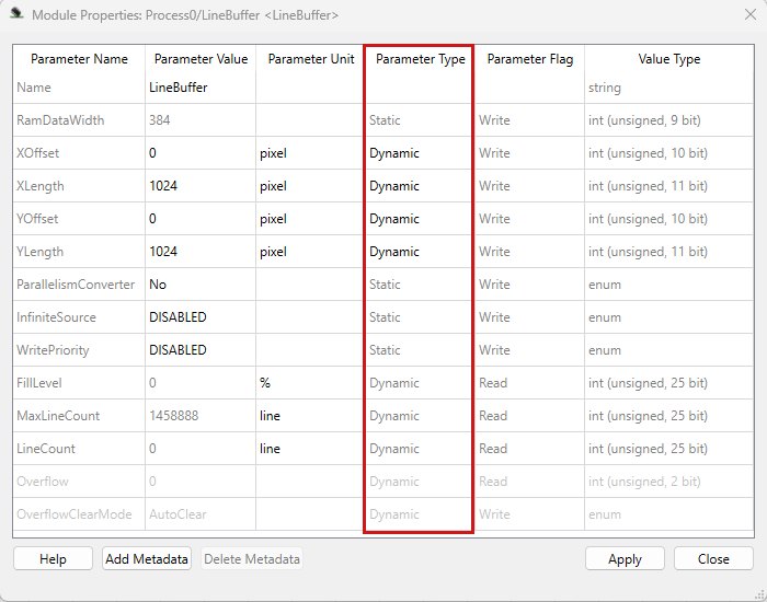
After you edit a parameter, click Apply in the Module Properties dialog. VisualApplets discards a new value if it isn't within the allowed range. Some parameters are disabled and can't be edited. Whether a parameter is enabled depends on other parameter settings, or on the input or output link format. For details about the module parameters of a specific operator, check the Operator Reference for the operator you use.
For a walkthrough that sets link and module parameters in a sample design, see Hardware Applet: From Idea to Application in the User Manual.
Dimension Parameters#
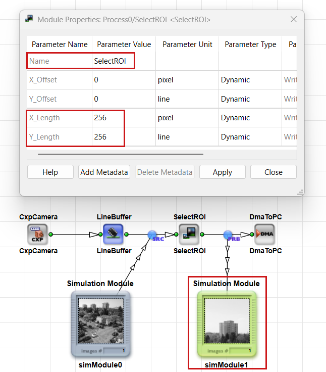
Many operators, such as LineBuffer, FrameBufferMultiRoi, and SelectROI, define a region of interest (ROI) through the parameters XLength, YLength, XOffset, and YOffset. The region of interest must fit within the maximum image dimensions on the connected links. If XLength + XOffset exceeds MaxImageWidth, or YLength + YOffset exceeds MaxImageHeight, DRC reports an error and the parameters are marked red.
In the following screenshot, the SelectROI operator defines an ROI through the XLength and YLength parameters:
Infinite Sources and the InfiniteSource Parameter#
Operators such as camera modules can't be stopped by flow control. They behave as infinite sources and must connect only to M-type operators that accept infinite sources, or to O-type and P-type operators that propagate the infinite-source property downstream.
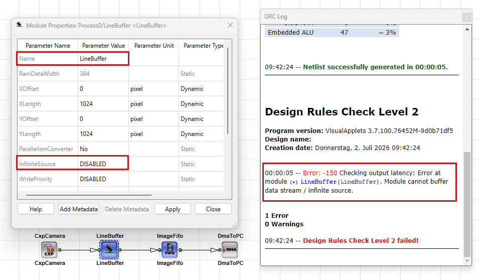
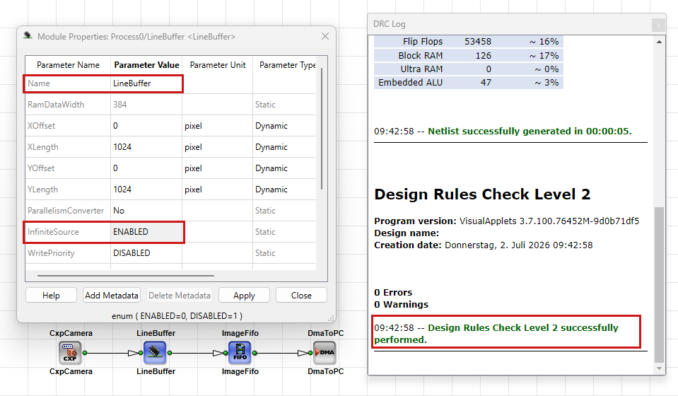
Buffer operators convert an infinite stream into a controllable, stoppable stream. When a buffer receives data from a non-stoppable source, set its InfiniteSource parameter to ENABLED. When the input is already a stoppable stream, set InfiniteSource to DISABLED.
Design Rules Check with InfiniteSource Set to DISABLED After an Infinite Source:
Design Rules Check with InfiniteSource Set to ENABLED After an Infinite Source:
For more detailed information about infinite sources, see Stoppable and Non-Stoppable Data Streams Tutorial topic.
The Overflow Operator#
The Overflow operator in the Synchronization library handles overflow situations when a non-stoppable source keeps sending image data while downstream processing is blocked. It doesn't buffer data itself. Basler recommends that you use it together with a buffer operator. This operator is not the same as arithmetic overflow (see Bit Arithmetic Tutorial topic) or the Overflow status parameter on buffer operators (see Memory Elements Tutorial topic).
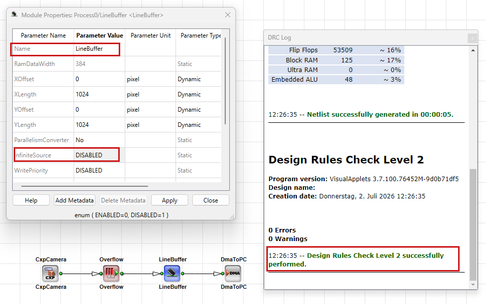
When you place Overflow between an infinite source and a memory operator such as LineBuffer, set InfiniteSource on the memory operator to DISABLED. The Overflow operator already handles overflow from the non-stoppable stream. Enabling InfiniteSource on the memory module in this topology is incorrect and triggers DRC errors.
Verifying Your Design with DRC#
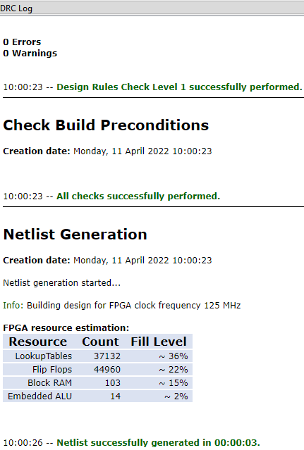
After you change link properties or module parameters that affect image size, bit width, or regions of interest, run Analysis → Design Rules Check Level 1. Level 1 reports formal errors in the DRC log and highlights affected modules and links.
Design Rules Check Level 2 runs extended checks and estimates FPGA resources. Fix all Level 1 errors before you build. Level 2 also checks infinite-source connections and InfiniteSource settings.
Read the DRC log together with highlighted modules and links. For the full workflow, see From Empty Design to Running Applet Tutorial topic.
Troubleshooting Link and Parameter Conflicts#
Module parameters and link properties aren't independent settings. They directly depend on each other and mutually limit their allowed value ranges. Link properties on the input and output connections define the data format that an operator must work with. Module parameters define how the operator processes data within that format. When you change a link property, VisualApplets propagates the change through successive modules and links. If a module parameter no longer fits the updated link properties, VisualApplets marks the module or the parameter in red. The same applies in the other direction: a module parameter can define or change output link properties, so a value that was valid before can become illegal after a link change. Whether a parameter is enabled, disabled, or limited to a specific range therefore depends on link properties, on other module parameters, or on both. For each operator, the Operator Reference documents these dependencies. For the propagation behavior and the three possible outcomes of a link change, see Propagation and Dependencies of Operator Parameters and Link Properties in the User Manual.
When a parameter value doesn't stick or a module turns red after a link change, resolve conflicts in this order: Check link properties before module parameters. Link properties define the allowed value range for module parameters. Module parameters must fit inside that range. Many operators also define or change output link properties, so a change on one side of the design can affect the other. Read the DRC log, click an error message to highlight the affected module or link, and consult the Operator Reference for the allowed link formats and parameter dependencies. Red highlighting on links or in the Module Properties dialog indicates a formal error that you must fix before simulation or build.
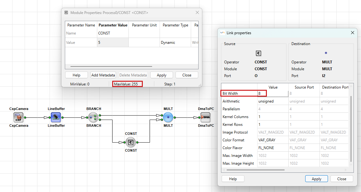
A typical conflict occurs when you try to set the Value parameter of a CONST operator e.g. to 500, but VisualApplets auto-corrects the entry. The outgoing link has a Bit Width of 8 bits, which allows only values from 0 to 255. To fix the conflict, increase the link Bit Width on the outgoing link, then set the module parameter again:
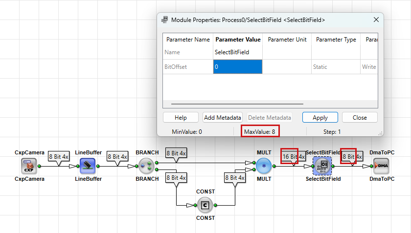
Similar dependencies appear with other operators. On SelectBitField, the valid range of the BitOffset parameter depends on the input and output link Bit Widths. For gray images, BitOffset must be in the range from 0 to input BitWidth minus output BitWidth:
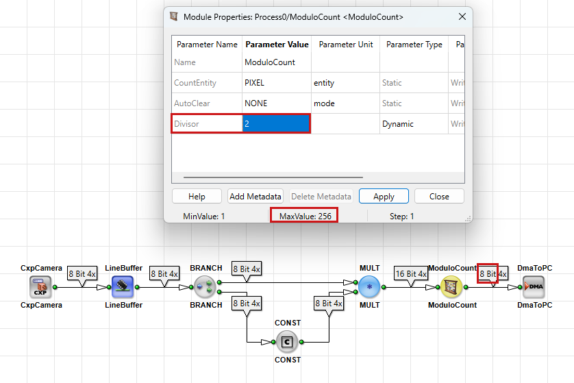
On the ModuloCount operator, the Divisor parameter is limited by the output link Bit Width to values from 1 to 2^n, where n is the output Bit Width:
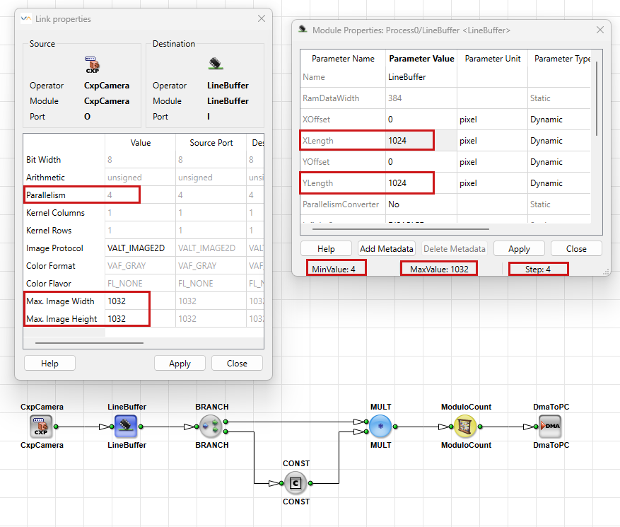
Region-of-interest parameters such as XLength and YLength must fit within MaxImageWidth and MaxImageHeight on the connected links. Conflicts can also involve parallelism, color format, and image protocol. For example, XLength must always be a multiple of the parallelism, which is indicated in the Module Properties dialog as Step Size:
Key Terms
Basler recommends the following practices when you work with parameters:
- Use dynamic parameters when you need runtime flexibility, for example for threshold values. Runtime means host software talking to the applet on the frame grabber, not simulation in VisualApplets.
- After each change to link properties or module parameters, check the propagated link properties on downstream links.
- Plan bit-width adjustments for downstream software, for example widening 12-bit camera data to 16 bits per pixel before the DMA.
- When a value can't be set, check link properties on the connected links before you change module parameters.
- Run DRC regularly to catch conflicts between links and modules early.
Related Topics#
- Parameterization in the User Manual — editing link properties and module parameters in the GUI
- Example: Applet Parameterization in Basics and Examples in the User Manual — worked parameterization example
- Rules of Links in the User Manual — formal link rules
- Parallelism Tutorial topic —
Parallelismlink property - Working with Kernels Tutorial topic —
KernelColumnsandKernelRows - Bit Arithmetic Tutorial topic —
BitWidthand arithmetic overflow - Stoppable and Non-Stoppable Data Streams Tutorial topic —
InfiniteSource - Operator Types and Synchronization Tutorial topic — operator types and link formats
- From Empty Design to Running Applet Tutorial topic — setting parameters at design time