Operator Types and Synchronization#
Key Terms
VisualApplets marks each operator with a shape that shows its type. Round icons are O-type operators. Square icons are M-type or P-type operators. M-type and P-type both use square icons, so you cannot tell them apart by shape alone. Check the in-product help or the Operator Reference for the type. The main difference: M-type operators can block their input; P-type operators do not actively block.
Blocking means a generated FPGA stage can pause its input when it isn't ready to accept more data. You can't connect two independent camera streams with a normal operator, because their timing differs. Use a synchronization operator with a buffer to synchronize the data streams.
Recognizing Operator Types#
VisualApplets groups operators into three types. You recognize the type by the module icon shape in the design pane. The in-product help and the Operator Reference document the type of each operator.
| Type | Shape | Main behavior |
|---|---|---|
| O-type | Round: |
|
| M-type | Square:  |
|
| P-type | Square:  |
|
Every source operator, such as a camera module, is an M-type operator. Every final destination, such as DmaToPC, is an M-type operator.
O-Type Operators#
O-type operators perform simple processing steps. They follow these rules:
- The number of pixels on the output equals the number of pixels on the input.
- There is a delay of a constant number of clock cycles between input and output. This timing delay must be compensated for during timing synchronization.
- You can assemble them in series or in parallel without restrictions. Splitting and merging O-type pipelines doesn't require any additional synchronization.
- They can't block the data stream themselves, but they propagate blocking conditions from downstream modules.
Info
Basler recommends that you prefer O-type operators where they fit your algorithm. They typically use fewer FPGA resources than M-type operators.
M-Type Operators#
M-type operators perform more complex processing. They follow these rules:
- They can change the number of pixels between input and output.
- They can delay the output.
- They can block the input when they aren't ready to accept more data.
- You must follow the link rules when you connect them.
- Merging data streams originating from different M-type sources is only possible using dedicated operators with asynchronous inputs (e.g.,
SYNC, orSourceSelector).
Camera operators and buffer operators are always M-type operators. Many filter and synchronization operators are M-type as well.
P-Type Operators#
P-type operators are similar to M-type operators. The main difference is that they don't actively block the input. They also don't reduce bandwidth on the link and don't generate more data than they receive. They can be used with non-stoppable sources.
Key Terms
A non-stoppable stream runs continuously. A non-stoppable source cannot be paused by the flow-control logic of the generated FPGA design. A typical example is a camera that keeps sending pixels. As a contrast, a stoppable stream can pause when the next operator isn't ready. A buffer between camera and downstream processing often turns a non-stoppable stream into a stoppable one.
For details on stoppable and non-stoppable data streams, see Stoppable and Non-Stoppable Data Streams Tutorial topic.
Unless an exception is specified in the Operator Reference, the same link rules apply to both P-type and M-type operators. However, unlike M-type operators, P-type operators can be used with non-stoppable sources.
Synchronous and Asynchronous Inputs#
M-type operators with multiple inputs accept synchronous inputs, asynchronous inputs, or both. Some operators provide groups of synchronous inputs which may be asynchronous to each other. The in-product help and the Operator Reference document which input type each port requires.
Synchronous Inputs#
Many operators require synchronous inputs on all or on a subset of their input ports. Synchronous means that the data streams on these inputs are aligned: The protocol, the number of incoming pixels, and the timing of the data must all match exactly.
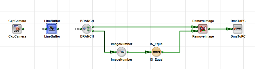
Synchronous behavior is guaranteed when all inputs originate from a common M-type source that is routed exclusively through a network of O-type operators. These inputs may be connected through any number of O-type operators, as long as no other source (i.e. M-type operator) is introduced.
All inputs that belong to the same synchronous group always share a single M-type source.
A typical example is RemoveImage with two image inputs from the same LineBuffer:
Asynchronous Inputs#
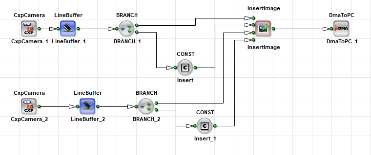
Only a small number of operators support asynchronous inputs. Asynchronous means that the data streams on these inputs are not aligned: The timing, protocol, and number of incoming pixels may differ. The specific properties that may differ between asynchronous inputs depend on the operator. Asynchronous inputs may also be connected through O-type operator networks from their respective sources. Use asynchronous inputs only with operators that explicitly support them. These operators convert asynchronous data streams into synchronous data streams.
Operators that support asynchronous image inputs include:
SYNCInsertLineInsertImageSourceSelector.
FrameBufferRandomRead and FrameBufferMultiRoiDyn also accept asynchronous image links, but their coordinate input must still be synchronous.
You can't merge two independent M-type sources with a normal multi-input operator. For this, you need an operator that supports asynchronous inputs:
Synchronization Rules#
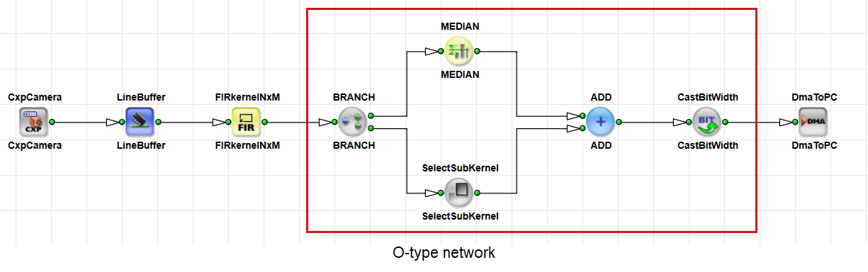
In an O-type network, all O-type modules, regardless of network complexity, must be sourced from the same M-type or P-type module. Links from this source can pass through other O-type modules or O-type subnetworks.
Splitting and merging O-type pipelines is straightforward and doesn't require additional synchronization.
When an M-type or P-type operator is introduced into the network, it becomes a new data source. If branches that originate from different sources are merged downstream, the merge requires synchronization, i.e., you must add an operator with asynchronous inputs, such as SYNC, InsertLine, InsertImage, or SourceSelector. These branches can't be connected to standard multi-input operators.
VisualApplets highlights synchronization violations with purple links in the design pane:
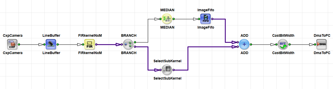
This O-type network rule ensures synchronous inputs: All branches that belong to the same synchronous input group must originate from a single M-type or P-type source and may only pass through O-type operators.
The O-type network rule doesn't apply to signal links that use Image Protocol = VALT_SIGNAL. For more information, see Differing Rules for Signal Links in the User Manual.
Merging Independent Sources#
When two or more independent sources feed one processing path, you must synchronize timing and image dimensions.
- Timing synchronization aligns when pixels arrive on each branch.
- Image dimension synchronization aligns width, height, and image protocol.
Synchronization is typically done using the operator SYNC. For certain situations there are a few other options for synchronization.
Incorrect timing synchronization can cause deadlocks, insufficient bandwidth, or data loss.
Info
To avoid deadlocks, place a memory operator, such as ImageFifo or ImageBuffer, before the SYNC operator when sources run at different speeds or when one branch adds delay. Memory elements must also be sized appropriately: You need to know the expected delay in order to choose a sufficient buffer size.
Deadlocks can't reliably be detected with simulation in VisualApplets, but appear only in hardware. To detect them, watch the FillLevel parameter of the ImageFifo operator or other buffer operators on the frame grabber, for example in microDisplay X. A FIFO that stays at 100% often indicates the source of a deadlock. You cannot observe that fill level in the VisualApplets design pane.
For more details on deadlocks, see Troubleshooting: Deadlock
When you merge asynchronous streams, ensure that line rate, frame rate, and pixel rate match. If one camera runs faster than another, a buffer fills until it overflows and data is lost. Use a trigger system when you need long acquisitions from multiple cameras at the same rate.
Synchronizing with the SYNC Operator#
The SYNC operator synchronizes timing and image dimensions on all input links. The number of inputs is fixed when you instantiate the operator. All outputs are synchronous. Downstream O-type operators can then process the merged streams.
The SYNC operator acts like a valve on all inputs. It waits until a valid pixel is present on every input. Then it forwards pixels on all outputs at the same time.
When input images differ in size, SYNC aligns them. Depending on the parameterization, it expands the smaller image or crops the larger one. See the operator description SYNC in the Operator Reference and section Using the SyncToMin and SyncToMax Parameter Values for SyncToMin and SyncToMax behavior.
Info
Use the SYNC operator near the camera in a design only when the cameras are triggered synchronously. Otherwise the buffers may fill up quickly.
A typical two-camera path looks like this:
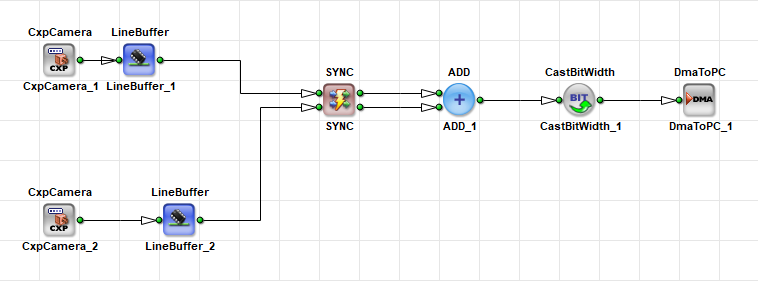
The buffers absorb timing skew between the cameras. Without buffers and without SYNC, the design risks deadlock or DRC warnings.
For a step-by-step overlay and stitching walkthrough, see Synchronization of Asynchronous Image Pipelines in the User Manual.
Using the SyncToMin and SyncToMax Parameter Values#
If sources contain images of different sizes, use the SyncMode parameter of the SYNC operator to align their dimensions. You can choose between the values SyncToMin and SyncToMax.
The synchronization ensures that all output images have the same size. The SYNC operator supports two modes:
-
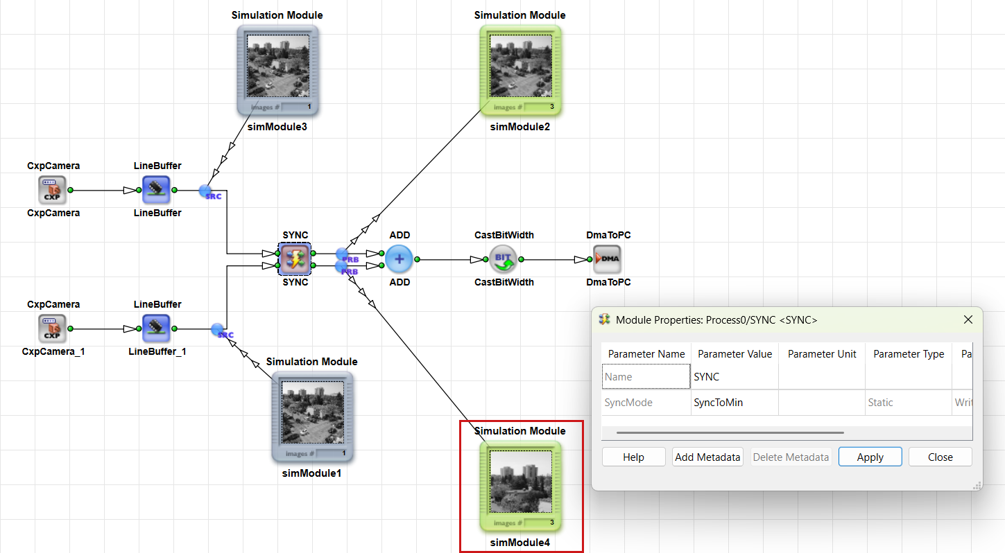
SyncToMin: Aligns all images to the smallest image size by cropping larger images.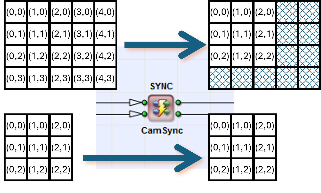
-
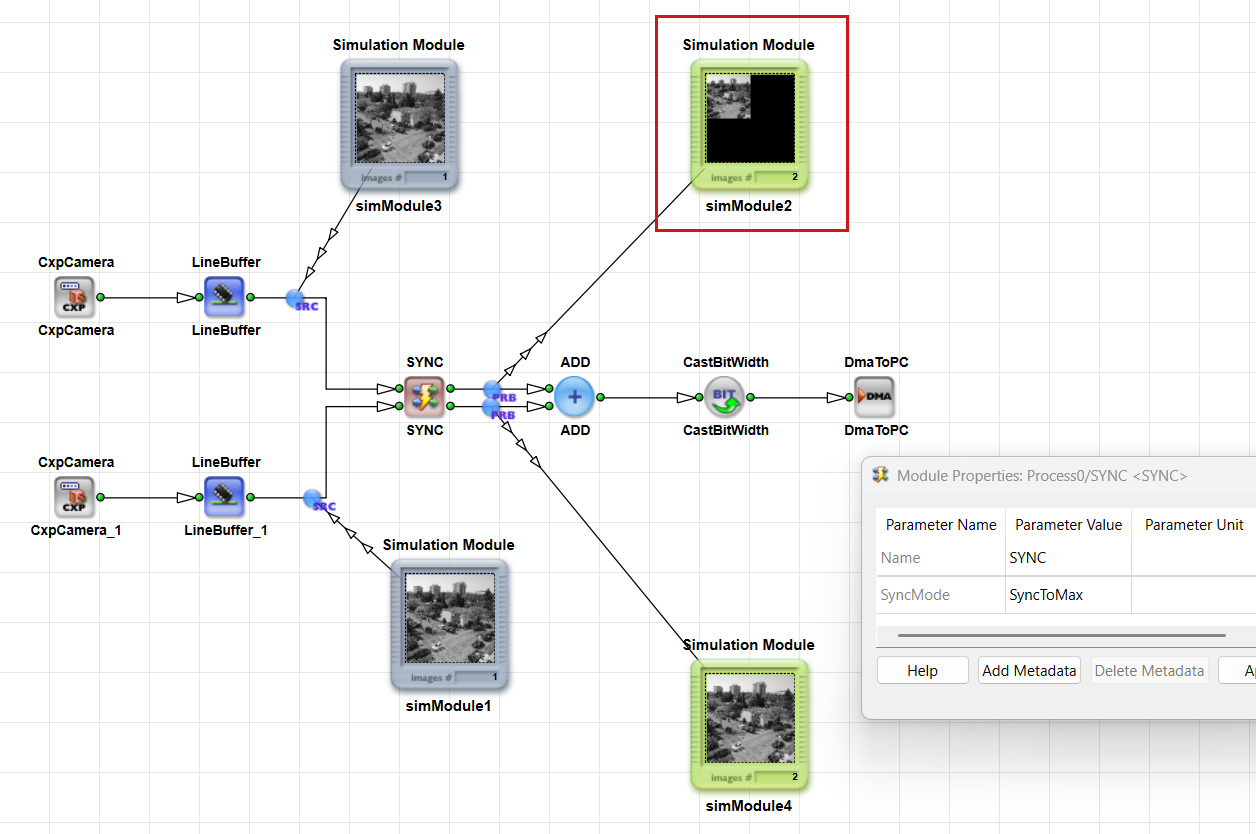
SyncToMax: Aligns all images to the largest image size by expanding smaller images. InSyncToMaxmode, any additional areas are filled with dummy zero pixels (displayed as black).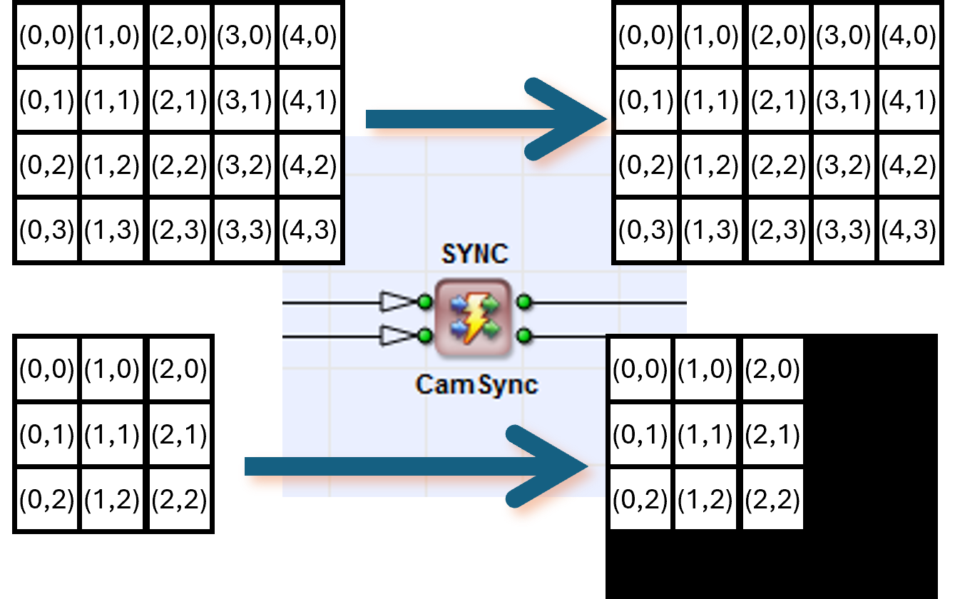
In the simulation, this looks as follows:
SyncToMin: The larger image is cropped.
SyncToMax: The smaller image is filled with dummy pixels.
Synchronizing with the InsertLine and InsertImage Operators#
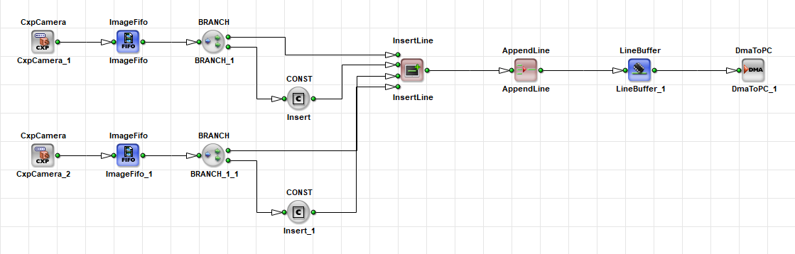
InsertLine assembles an image by inserting lines from several sources. Use it for line-based stitching when both sources deliver lines in sequence.
When the cameras are triggered synchronously, you can use a smaller ImageFifo operator instead of a LineBuffer operator. This reduces resource usage.
Info
InsertLine and InsertImage are often used together with the CONST operator. In this context, CONST specifies whether the image or line is included in the output stream. The data is always processed, but CONST determines whether it appears in the output stream or is discarded internally (i.e., sent to an internal trash path).
InsertImage assembles a sequence of images by inserting images from several sources. Use it to multiplex images from two cameras into one output sequence.
Both operators accept asynchronous inputs. If these operators are used with non-stoppable sources, place buffers with sufficient size before them to avoid a deadlock. See also InsertLine in the Operator Reference and InsertImage in the Operator Reference.
Synchronizing with the SourceSelector Operator#
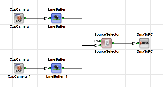
SourceSelector selects between multiple image sources, for example two cameras. It switches between asynchronous sources while maintaining the integrity of the incoming images.
Only the selected input is forwarded to the output; all other inputs are discarded. If a switch occurs while an image is still being transferred on an input, the transfer is completed before the new source becomes active.
Use the SelectSource parameter to control the active source at runtime.
The operator finishes the current frame before it switches to another input. Set InfiniteSource to ENABLED when a camera feeds the input. Set it to DISABLED when the input comes from a buffered, stoppable stream.
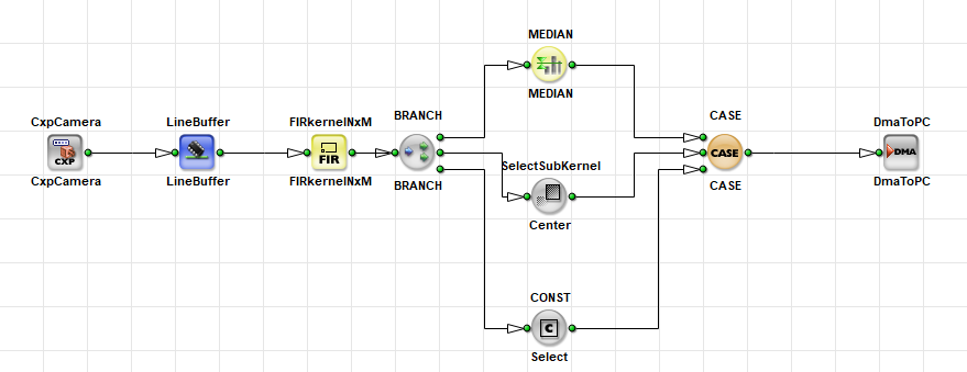
Basler recommends that you use IF or CASE instead of SourceSelector when all inputs are sourced from the same M-type module. Those operators use fewer resources. See for example the following design with a CASE operator:
See also SourceSelector in the Operator Reference.
Avoiding Synchronization#
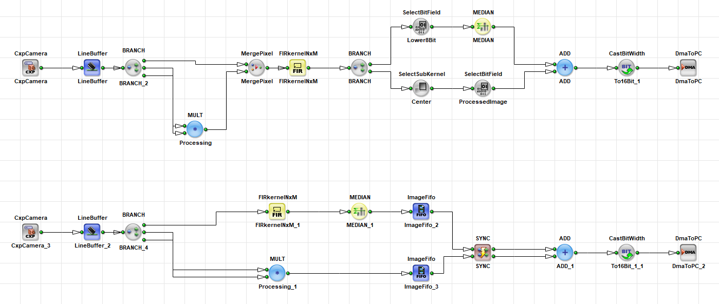
As operators for synchronization and buffering consume a lot of FPGA resources, avoid the need for synchronization whenever possible. In many cases this can be done by applying alternative design techniques. Such techniques may include merging data before required M-type operators and splitting the data afterwards. The following screenshot shows two implementations of similar workflows, once using MergePixel and ADD, and once using SYNC:
Troubleshooting: Deadlock#
One of the most common and most difficult synchronization errors is a deadlock.
A deadlock occurs when two sources are synchronized directly, for example, by using a SYNC operator, without any buffering. In this situation, each source waits for the other: A waits for B, and B waits for A. As a result, no data is transferred.
The diagram below shows a branch module on the lower path that receives a stop signal and therefore no longer accepts data at its input. As a result, the upper path also stops receiving data, and the entire pipeline halts:
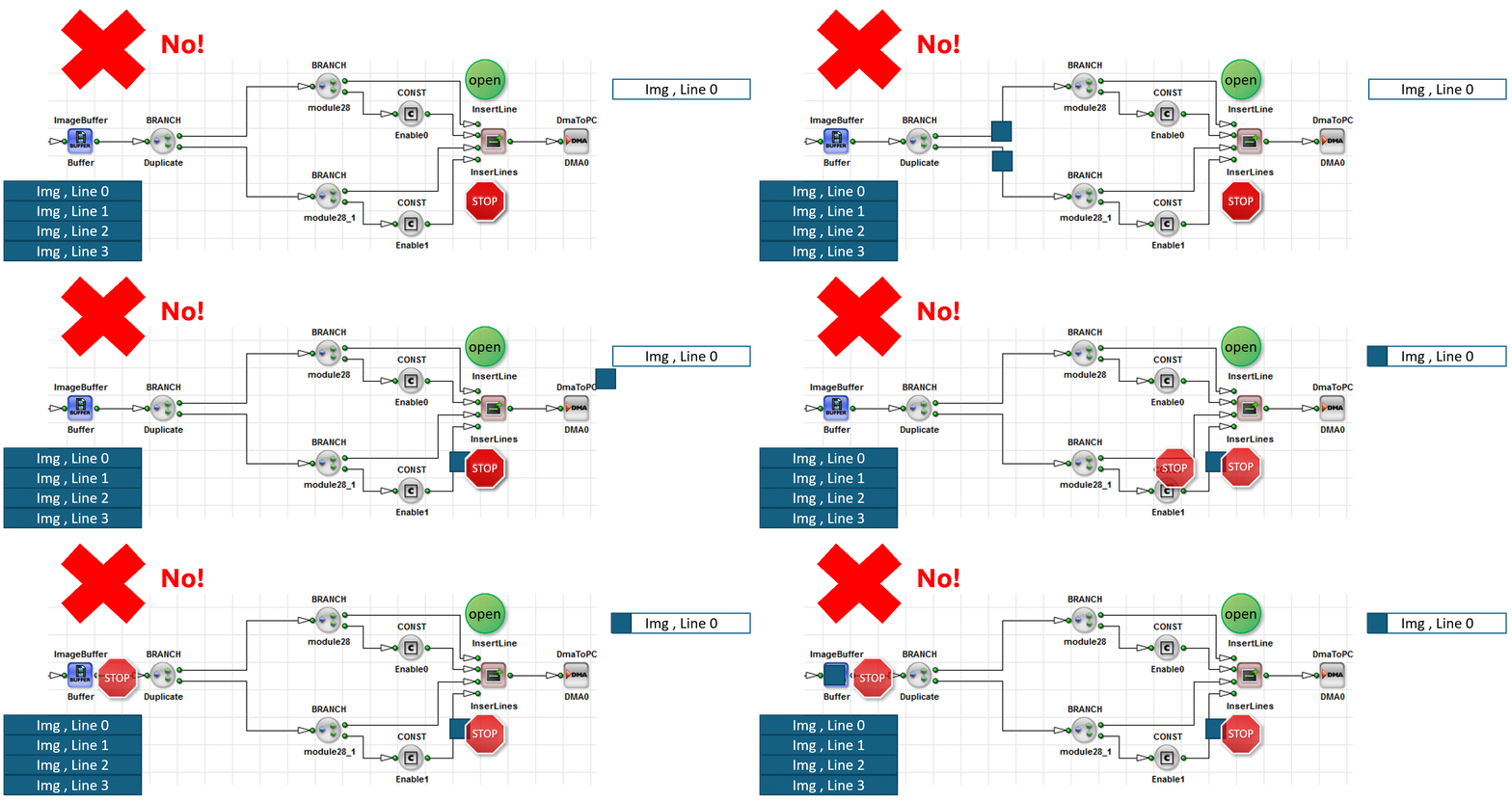
Deadlocks are often not visible in simulation, where the system may appear to run normally. On hardware, however, they typically result in no output. In such cases, the hardware applet freezes, stops transferring data to the PC, and eventually causes a DMA timeout.
Info
Deadlocks are difficult to detect because they are often not visible in simulation. To identify a possible deadlock, monitor the FIFO fill levels in hardware using runtime tools such as microDisplay X. A FIFO that remains at 100% capacity indicates a possible deadlock or a bottleneck.
Typical causes for a deadlock:
- Missing buffers
- Incorrect synchronization
How to fix a deadlock:
To fix a deadlock, insert FIFO-based buffering, for example, ImageBuffer or ImageFifo, before the SYNC operator. This allows one source to run slightly ahead and prevents the mutual wait condition:

Verifying Your Design with DRC#
Run Analysis → Design Rules Check Level 1 after you wire branches that merge. Level 1 reports synchronization violations and marks affected links in purple.
Design Rules Check Level 2 runs extended checks and estimates FPGA resources. Fix formal errors from Level 1 before you build.
Read the DRC log together with highlighted modules and links. For the full workflow, see From Empty Design to Running Applet Tutorial topic.
Related Topics#
- Rules of Links in the User Manual — O-type network rule and signal links
- Stoppable and Non-Stoppable Data Streams Tutorial topic — infinite sources and flow control
- Memory Elements Tutorial topic — buffers before
SYNC - Pipeline Concept Tutorial topic — blocking and backpressure
- Synchronization of Asynchronous Image Pipelines in Basics and Examples
- From Empty Design to Running Applet Tutorial topic — DRC, simulation, and build
- Parameterization Tutorial topic — link properties at merge points