Parallelism#
Key Terms
The Base Design Clock is the clock of the generated FPGA pipeline on the frame grabber, for example 312.5 MHz. It is not the same as the camera pixel clock, and it is not a clock inside the VisualApplets editor. A clock cycle is one tick of the Base Design Clock. Per clock cycle, a certain number of pixels can pass through a link. That number is parallelism. Parallelism 4 means four pixels per clock cycle. A higher Base Design Clock frequency or higher parallelism increases the pixel rate, which this topic calls bandwidth.
Parallelism and Bandwidth#
Parallelism is the number of pixels that flow per clock cycle through a link of the generated FPGA pipeline.
Parallelism affects the processing granularity inside modules. For example, the LineBuffer parameter XLength depends on parallelism.
The following rules apply:
- Higher parallelism → higher pixel-rate bandwidth.
- Higher parallelism → higher FPGA resource usage.
Bit width and kernel size are not part of this pixel-rate number. They increase the amount of data per clock, which matters for DRAM and resources. See Working with Kernels Tutorial topic and Memory Elements Tutorial topic.
Design Guideline
Keep parallelism no higher than necessary to save FPGA resources.
The bandwidth of a link as a pixel rate follows this formula:
Bandwidth = parallelism × Base Design Clock
The Base Design Clock depends on the frame grabber you use. For Basler frame grabbers, look up the value in Device Resources.
Key Terms
You can make the parallelism and the data throughput visible in your design by using the Link Info and the Throughput flags. Activate these flags with the following buttons from the toolbar:

As a result, the Link Info and Throughput flags are displayed in your design:
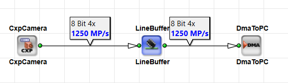
In this topic, we show all screenshots of the designs with the Link Info and Throughput flags enabled.
Calculating the Required Parallelism#
To dimension a design, first calculate the required pixel rate, then derive the required parallelism from the Base Design Clock.
Calculating the Parallelism for Area Scan Designs#
For designs with area scan cameras, first calculate the bandwidth in pixels per second:
Bandwidth = (pixels per line) × (lines per frame) × frame rate
Then use the bandwidth to calculate the required parallelism:
Required parallelism = bandwidth / Base Design Clock
Select the smallest supported parallelism that is at least as large as the calculated requirement. Rounding down would leave the design below the required bandwidth. For example, 6000 MP/s at a Base Design Clock of 312.5 MHz needs a parallelism of 19.2. Parallelism 19 would provide only 5937.5 MP/s, which is not enough. Use 20, or the next higher value that your platform allows.
Area Scan Calculation Example#
For a camera with resolution 2064 × 2064 pixels and 30 frames per second, the following bandwidth calculation applies:
Bandwidth ≈ 2064 × 2064 × 30 ≈ 127.9 MP/s
With a Base Design Clock of 312.5 MHz, this leads to the following calculated parallelism:
Required parallelism ≈ 127.9 / 312.5 ≈ 0.41 → round up to 1

The screenshot above shows the corresponding VisualApplets design implementation. The parallelism at the camera interface is set to 4. That value is not the processing parallelism from the bandwidth calculation. The CxpCamera operator sets interface parallelism automatically from the number of CXP connections defined by the ConnectionCount module parameter (in this case, x1). Interface parallelism and required processing parallelism are different numbers. Since the required processing parallelism is 1, the link parallelism is reduced to 1 at the output link of the LineBuffer operator.
At low frame rates, a parallelism value of 1 is sufficient. At higher frame rates or resolutions, the required parallelism increases. Calculate the value and then round it up to the next supported level, for example: 2, 4, or 8. If the platform requires an even parallelism, round up first, then select the next higher valid even value. For example, if the calculation results in 6.3, use 8, and not 7.
Calculating the Parallelism for Line Scan Designs#
For designs with line scan cameras, first calculate the bandwidth in pixels per second:
Bandwidth = (pixels per line) × line rate
Then use the bandwidth to calculate the required parallelism:
Required parallelism = bandwidth / Base Design Clock
Round the result up according to your platform rules and the allowed parallelism values.
Line Scan Calculation Example#
For a camera with resolution 16384 pixels and 120 kHz line rate, the following bandwidth calculation applies:
Bandwidth ≈ 16384 × 120 kHz ≈ 1966.08 MP/s
With a Base Design Clock of 312.5 MHz, this leads to the following calculated parallelism:
Required parallelism ≈ 1966.08 / 312.5 ≈ 6.3 → round up to 7
The calculation yields 6.3, so the next integer is 7. If the platform requires an even parallelism, select the next higher valid even value (8, not 7). The screenshot below uses parallelism 7, which is valid when even parallelism is not required.

The screenshot above shows the corresponding VisualApplets design implementation. The parallelism at the camera interface is set to 12. This value is automatically configured by the CxpCamera operator from the number of CXP connections (ConnectionCount parameter set to x2). That interface parallelism is again not the same as the required processing parallelism. The SplitImage operator performs a 1D-to-2D conversion. The LineBuffer operator then reduces the link parallelism to 7 to match the calculated processing requirement.
Changing the Parallelism in a Design#
The operators below adapt the parallelism of a design to the bandwidth requirements:
Increasing or Decreasing the Parallelism#
PARALLELdn— reduces parallelism. See PARALLELdn in the Operator Reference.PARALLELup— increases parallelism. See PARALLELup in the Operator Reference.- LineBuffer (imaFlex only): The
ParallelismConverterparameter of theLineBufferoperator adjusts parallelism between input and output without additional parallelism operators. See LineBuffer (imaFlex) in the Operator Reference.
Splitting, Selecting, and Merging Streams#
SplitParallel— Splits one data stream with a higher parallelism into several streams with lower parallelism. Example: Parallelism8becomes two streams with parallelism4each. See also SplitParallel in the Operator Reference.SelectFromParallel— Selects individual components from a parallel stream, for example one data word out of several transferred per clock cycle. See also SelectFromParallel in the Operator Reference.MergeParallel— Merges parallel streams again after separate processing. See also MergeParallel in the Operator Reference.
Other Operators#
CastParallel— Reinterprets bits on the link. Parallelism and bit width may change as long as bit width × parallelism stays equal at input and output. Example: 16 bit × PAR 2 becomes 8 bit × PAR 4. Image width changes accordingly. See also CastParallel in the Operator Reference.ExpandToParallel— Takes an input with parallelism 1 and produces the desired output parallelism. The input value is replicated to all parallel channels. See also ExpandToParallel in the Operator Reference.
Use Cases#
The following use cases appear frequently:
-
Use
PARALLELupto increase parallelism, process data in parallel branches, and merge the branches again withMergeParallel.
-
For certain processing tasks, selecting just one component is mathematically sufficient and provides the required results while reducing the data amount. Use
SelectFromParallelto forward only one channel from a parallelism4stream.

- After
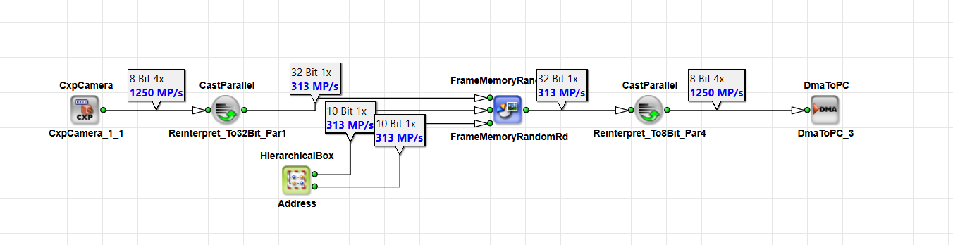
FrameBufferRandomRead, the stream runs at parallelism1with, for example, 64 bit per pixel. In order for downstream processing to run at higher parallelism, reinterpret the data stream as 8 bit × parallelism8. For this, use theCastParalleloperator.
- Use
ExpandToParallelto expand a control value or pixel stream with parallelism1to parallelism4when the same value must be available in all four parallel channels, for example for coefficients or masks in parallel branches.

Parallelism Constraints#
The maximum image width in pixels must be divisible by the parallelism.
Examples:
- With parallelism
4, allowed image widths include 1024 and 2048. - With parallelism
12, an image width of 16384 is not allowed because 16384 / 12 is not an integer.
Workarounds:
- Dummy pixels — widen the image, for example through simulation link properties or operators, until the image width divides evenly by the parallelism value.
- Crop — trim the image to a valid image width.
Key Terms
The generated FPGA hardware processes pixels in packets per clock. A line of 16384 pixels doesn't pack cleanly into parallelism 12, because 16384 / 12 is not an integer. VisualApplets therefore requires that the image width in the design is divisible by the parallelism.
Parallelism with Memory Operators#
FrameBufferRandomRead allows only parallelism 1, because memory is accessed sequentially. To use higher parallelism in the design and to not influence the overall bandwidth, convert the parallel components to kernel components using the CastKernel operator or to higher bit components of the current pixel using the CastParallel operator.
See the Working with Kernels Tutorial topic for an example of how to do this.
See FrameBufferRandomRead in the Operator Reference and FrameBufferRandomRead (imaFlex) in the Operator Reference.
Troubleshooting Bottlenecks#
A typical bottleneck arises when InsertLine in the Operator Reference or InsertImage in the Operator Reference isn't combined with PARALLELup. If the operator order is unfavorable, throughput can drop.
Using insert operators increases the amount of data fed into a processing pipeline, which raises the overall bandwidth. Therefore, the parallelism after the InsertLine or InsertImage operator must be high enough to handle the resulting bandwidth.
Example#
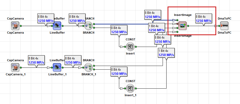
The example in the image above shows that the InsertImage operator has two input links. Each input link processes images with a resolution of 5120 × 5120 pixels at a bandwidth of 1250 MPixel/s, using a parallelism of 4.
If the parallelism isn't increased before the InsertImage operator, the bandwidth per input remains 1250 MPixel/s. However, because there are two input links, the design must process a combined throughput of 2 × 1250 MPixel/s.
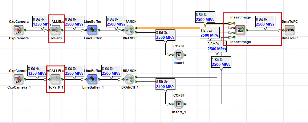
To avoid this bandwidth bottleneck, increase the parallelism using the PARALLELup operator before the InsertImage operator as shown below:
Related Topics#
- Pipeline Concept Tutorial topic — throughput, bottlenecks, and link capacity
- Parameterization Tutorial topic —
Parallelismlink property - Memory Elements Tutorial topic — RAM data width and
LineBufferparallelism conversion - Working with Kernels Tutorial topic — kernel size versus parallelism
- Latency Tutorial topic — parallelism and latency
- Bandwidth of an Applet in the User Manual — formal bandwidth definition
- Device Resources — Base Design Clock frequencies
- Bandwidth Bottlenecks in the User Manual — operator ordering and bottlenecks