Pipeline Concept#
For the formal data flow model, see Data Flow in the User Manual. For how you build and verify a design end to end, see From Empty Design to Running Applet Tutorial topic.
Modules, Links, and Pipeline Structure#
You build a VisualApplets design from operators in the operator libraries. Each placed operator instance is a module. Modules expose input and output ports. You connect ports with links. The diagram shows each link as an arrow.
Together, modules and links in the VisualApplets design form the image-processing pipeline. The build implements that graph as hardware stages on the frame grabber FPGA. Processing order follows the connection order. Branches and merges define parallel paths and reunion points in the graph.
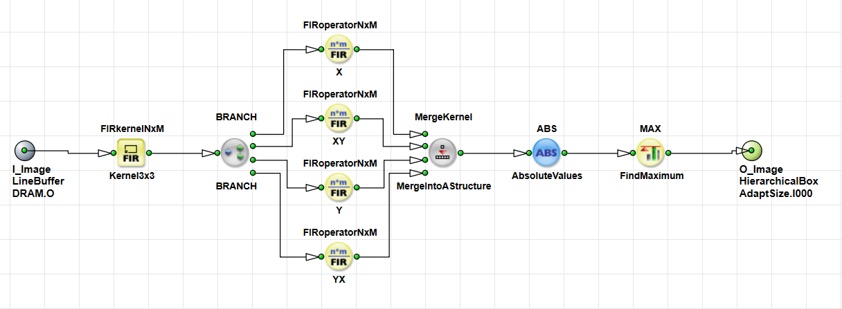
Each module starts processing as soon as input data is available. It forwards results on its output links when the calculation is complete and the output isn't blocked. At runtime, this behavior is implemented by the FPGA logic generated from the module, not by the graphical symbol in VisualApplets. The pipeline structure therefore defines where data splits, where it reunites, and which modules run in series or in parallel.
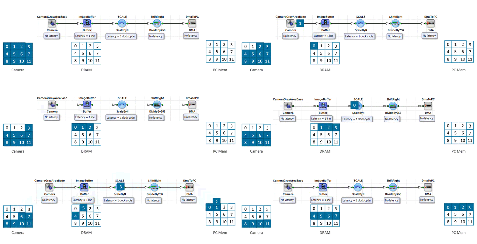
Pixels don't enter the frame grabber as a complete image in one step. The camera transfers them one after another into the acquisition path — or an applet-internal image source generates them one after another. Those pixels then pass through the pipeline stages in the same sequential order:
Key Terms
Think of pixels like cars on a road: they follow each other along the path. At any moment, different cars (pixels) are at different positions on the road (pipeline stages). The road itself is the pipeline structure you wired in the VisualApplets design. After the build, that road is hardware on the frame grabber FPGA, not a path inside the VisualApplets editor.
In this analogy, parallelism is the number of lanes on the road: with more lanes, more cars (pixels) can move forward at the same time.
Pipeline Inputs and Outputs#
Every pipeline has at least one source that feeds data into the design and one or more sinks that leave the FPGA processing path. Sources and sinks are usually M-type operators. Which operators are available depends on your target hardware platform.
Inputs#
Data can enter the pipeline in these ways:
- From a camera or other image source: Platform-specific camera operators deliver the continuous pixel stream from a connected camera into the acquisition path.
- Generated inside the applet: Operators such as
CreateBlankImageorCoefficientBuffercreate or play back image data without a live camera. You use these sources for test patterns, reference data uploaded from the host, or designs that don't acquire from a camera.
Signal paths can also start from digital inputs (for example via GPI) or from applet-internal signal generators. For how camera sources differ from stoppable applet-internal sources under flow control, see Stoppable and Non-Stoppable Data Streams Tutorial topic.
Outputs#
Processed results can leave the pipeline in these ways:
- DMA to the host: The
DmaToPCoperator transfers image data to host PC memory by direct memory access. This is the usual path for acquiring processed images in host software. - Signal via GPO: The
GPOoperator drives a digital output pin on the frame grabber. Use this path for trigger, status, or other hardware control signals outside the host PC. - Event to the host: The
EventToHostandEventDataToHostoperators send software events to the host. Host applications receive them through the Framegrabber API and can react to conditions in the applet.EventToHostraises an event on a rising edge at a signal input and carries no payload.EventDataToHostraises an event together with a configurable data payload. - Register information only: Some results stay on the frame grabber as readable values. Operators such as
GetStatusstore values that host software reads as dynamic parameters. No image stream or DMA transfer is required when the application only needs status or measurement numbers.
A design can combine several of these outputs. For example, one branch can send images through DmaToPC while another branch asserts a GPO pin or raises a host event when a condition occurs.
For operator details, see DmaToPC in the Operator Reference, GPO in the Operator Reference, EventToHost in the Operator Reference, EventDataToHost in the Operator Reference, and GetStatus in the Operator Reference.
Unbuffered Pipeline Flow#
Most modules don't store a full image internally. They calculate output values and forward them immediately when the information is available.
Not all operators output a result as soon as data arrives at the input. M-type operators in particular can delay the output. These aren't only buffer operators such as LineBuffer or ImageFifo — many filter and synchronization operators are M-type as well. How large the latency is depends on the operator. For details, see the Operator Types and Synchronization Tutorial topic and the Latency Tutorial topic.
Buffer operators store data until downstream modules can accept it.
This unbuffered behavior keeps latency low. A pixel can reach the output while other pixels of the same frame are still at the camera input. Acquisition, processing, and DMA can overlap in time.
Key Terms
Think of the generated FPGA pipeline like a system of pipes with branches and valves. Water flows through the pipes as soon as space is available. A buffer operator is like a small reservoir that fills when the drain can't keep up.
For how latency builds up along a path, and for the difference between bandwidth and latency, see Latency Tutorial topic.
Concurrent Processing in Hardware#
On the frame grabber FPGA, all pipeline stages run at the same time. This differs from a typical CPU program that executes instructions largely one after another.
While one FPGA module processes a pixel, other modules process different pixels farther along the path. After the pipeline has filled, multiple modules work on the same image concurrently. The FPGA implements your VisualApplets design as dedicated hardware whose structure matches the pipeline graph.
Key Terms
In the FPGA hardware generated from a VisualApplets design, the processing path is implemented as dedicated hardware logic on the frame grabber. Data moves through those hardware stages like items on a conveyor. A CPU usually loads whole chunks of data and works through steps in sequence.
For details about how the built applet relates to the editable *.vad design, see VisualApplets Fundamentals Tutorial topic.
Throughput and Bottlenecks#
Throughput is the sustained data rate through the pipeline. In a VisualApplets design it is closely related to bandwidth on the links of the generated FPGA hardware.
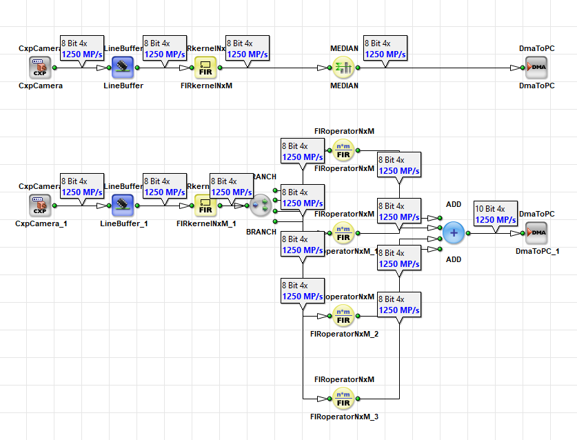
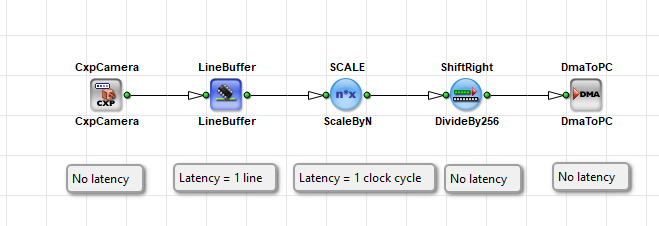
The number of modules in a design doesn't reduce the throughput. All generated FPGA stages can run in parallel. The number of parallel branches doesn't reduce throughput either. Branches add hardware resources, but they don't slow the data rate on an individual path by themselves. Two acquisition paths can use a different number of modules and still deliver the same throughput, as you can see in the following two designs:
Throughput depends on these factors:
- Link capacity: How much data a connection between modules can carry. Capacity is set by the parameterization of modules and links, especially parallelism, bit width, and maximum image dimensions, together with the Base Design Clock. See the Parameterization Tutorial topic for details about link properties and module parameters.
- Downstream readiness: Whether modules can accept data continuously. If a module can't take data permanently, for example because a buffer is full or a successor blocks, flow control stops the stream, which leads to blocking, backpressure, or both.
- Operator limits: Some operators can't process the full bandwidth that their input link provides. The Operator Reference documents these limits for each affected operator.
The bandwidth of a link as a pixel rate (pixels per second) follows this formula:
Bandwidth = parallelism × Base Design Clock
This pixel-rate formula does not include bit width or kernel size. A wider bit width or a larger kernel increases the amount of data per clock (bits or values), which matters for DRAM access and FPGA resources, but it does not change this pixel-rate number. For DRAM data width, see the Memory Elements Tutorial topic. For kernels versus pixel-rate bandwidth, see the Working with Kernels Tutorial topic.
The Base Design Clock depends on your frame grabber platform. Look up the value in Device Resources.
Maximum image dimensions also don't appear in this pixel-rate formula, but they still shape the design: they constrain which image sizes the pipeline can handle. Together with parallelism and bit width, these link properties must match your camera or line scan source.
The bottleneck of a path is the lowest bandwidth along that path. The overall throughput of the design is always limited by this narrowest point. One narrow link or one bandwidth-limited operator limits the throughput for everything upstream of it on the same path. Throughput is therefore set by the narrowest bandwidth on the path and by whether downstream modules accept data continuously.
Design Guideline
Configure parallelism and link properties only as high as needed to support the rate required by your camera or line scan source. Increasing these values further consumes additional FPGA resources and does not improve throughput if another component is already the bottleneck.
Some operators change the parallelism between their input and output. Others reduce the number of pixels, for example by cropping an image. As a result, the required output bandwidth can differ from the input bandwidth. Where possible, operators automatically adapt the parallelism. If adaptation is not possible, VisualApplets reports a Design Rules Check error.
For information about calculating and adjusting parallelism, including examples of how to calculate the required bandwidth for your design and how to troubleshoot bandwidth bottlenecks when operators merge streams, see the Parallelism Tutorial topic and Troubleshooting Bottlenecks Tutorial topic.
Visualizing Throughput in the Design#
You can make the parallelism and the data throughput visible in your design by using the Link Info and the Throughput flags. Activate these flags with the following buttons from the toolbar:
As a result, the Link Info and Throughput flags are displayed in your design:
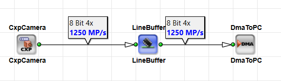
Compare the values along a path to find the narrowest link. That link is the bottleneck for the path unless an operator further downstream can't keep up.
Info
The Throughput flags don't show all performance limitations. For example, when multiple DRAM operators share the same memory interface, the resulting DRAM bandwidth limit from Shared Memory isn't reflected in the throughput display. Other DRAM inefficiencies, as well as blocking and potential deadlocks, are also not shown. For guidance on Shared Memory usage and DRAM bandwidth planning, see the Memory Elements Tutorial topic. For details on deadlocks, see the Operator Types and Synchronization Tutorial topic.
Link Properties and Image Formats#
Throughput and data format depend on link properties and module parameters. Besides the capacity-related properties covered above (parallelism, bit width, and maximum image dimensions), other typical properties include image protocol and color format.
Link properties propagate through the pipeline. You set many properties on the camera output link or on an early processing stage. They apply to all downstream links until an operator changes them. Module parameters must match the link properties on the connected links. Changes on an upstream link therefore affect all following operators until another operator resets a property.
For the full list of link properties and propagation rules, see the Parameterization Tutorial topic and Rules of Links in the User Manual.
The image protocol defines the structure of the data stream on a link. VisualApplets supports different data types / stream formats:
| Protocol | Typical use |
|---|---|
VALT_IMAGE2D | Two-dimensional images with end-of-line and end-of-frame markers, for example from area scan cameras. Lines within a frame can have different lengths. |
VALT_LINE1D | Endless or continuous line data, for example from line scan cameras. |
VALT_PIXEL0D | Unstructured continuous pixel streams without image dimension information. |
VALT_SIGNAL | Single-bit signals valid at every clock cycle, for example in trigger logic. |
Pixels move through the pipeline in scan order: left to right within a line, then top to bottom within a frame. Some camera sources use a different order. Use the appropriate operators to correct the order when your source doesn't match this convention.
For more information about image protocols and pixel order, see Image Protocols, Image Dimensions and Data Structure in the User Manual.
Whether a source can pause under flow control affects how you wire the pipeline. Camera operators are non-stoppable sources. You often place a buffer operator directly after them. For details, see Flow Control, Blocking, and Backpressure below and the Stoppable and Non-Stoppable Data Streams Tutorial topic.
Flow Control, Blocking, and Backpressure#
The generated FPGA pipeline applies flow control between stages. When a stage isn't ready to accept more data, it can block its input: it stops requesting data from the upstream stage, and the upstream stage stops outputting. That blocking propagates backward through the pipeline as backpressure. Note that only M-type operators can block the input. The graphical modules in VisualApplets describe this hardware behavior; they do not apply flow control themselves.
Suppose DmaToPC can't transfer data to the host computer fast enough. It blocks its input from time to time. The blocking signal propagates upstream to a buffer operator. The buffer stops forwarding data while blocking is active. It stores incoming pixels and its fill level rises. When the camera stops sending data, the buffer drains again.
Buffer operators decouple stages that process at different rates. Without a buffer after a non-stoppable camera source, blocking by downstream modules can't slow down the camera stream. As a result, the design may fail Design Rules Check or deadlock on hardware.
For operator types and how blocking behaves on O-type, M-type, and P-type modules, see the Operator Types and Synchronization Tutorial topic.
Key Terms
Blocking means a generated FPGA stage can't accept further input data, for example because the successor doesn't accept data or because processing inside the stage takes more time. The module icon in VisualApplets represents that stage; the icon itself does not wait or block.
Backpressure is the mechanism behind that: the "pressure" acts backward. If one stage doesn't take data fast enough, upstream stages must wait and the flow is blocked. In practice: A downstream stage can't accept data (for example, because a buffer is full), hence the upstream stage waits.
Bandwidth in this topic is the pixel rate of a connection: how many pixels per second fit through the link. Bit width and kernel size change how much data each of those pixels carries, which is a different quantity. See Parallelism Tutorial topic.
Related Topics#
- Data Flow in the User Manual — formal pipeline data-flow model
- VisualApplets Fundamentals Tutorial topic — design versus hardware applet
- From Empty Design to Running Applet Tutorial topic — design, DRC, simulation, and build
- Parallelism Tutorial topic — bandwidth and parallelism
- Latency Tutorial topic — delay along the pipeline
- Parameterization Tutorial topic — link properties and image formats
- Stoppable and Non-Stoppable Data Streams Tutorial topic — flow control and camera sources
- Operator Types and Synchronization Tutorial topic — operator types and blocking
- Operator Reference