Basler Light Bar-17x100-UV#

Info
The photo may slightly differ in appearance from the actual product.
Key Features#
- Integrated Light Control (ILC): Direct light control via Basler camera, eliminating the need for an external light controller.
- Integrated LED driver with two light control modes:
- Trigger Control Mode for hardware-based triggering
- Integrated Light Control Mode for camera-based configuration and automatic synchronization
- Overdrive option in both light control modes:
Increased light output without requiring additional hardware (see Overdriving Light Devices) - Automatic light detection: Camera automatically identifies the connected Basler Light and applies appropriate operating and protection settings.
- GenICam-compliant control via Basler cameras: Full control of brightness, strobe and continuous-light operation directly from a Basler camera using any GenICam-compatible software, such as the pylon Software Suite
- Integrated protection mechanisms: Over-triggering and thermal overload protection ensure reliable operation and protect the light throughout its service life.
- Support for external controllers: Can also be operated in External Control Mode via any external light controller.
Basler Lights Before and After Revision 05#
Info
To determine whether a Basler Light has Integrated Light Control (ILC), check the revision number on the light. The last two digits following the order number indicate the revision. In the example 2200000841-05, the revision is 05.
- Revision 05 or later: The light has ILC and an integrated controller.
- Revision below 05: The light doesn't have ILC. It requires an external light controller.
Documentation for Basler Lights without ILC is no longer included in the current Basler Product Documentation. For information about these lights, download the offline documentation of an earlier version by clicking here.
Changes to the Pin Assignment#
Info
Basler Lights with revision 05 or later use a different pin assignment than Basler Lights with a revision below 05.
Adjust the pin assignment when both of the following are true:
- You replace a Basler Light with a revision below 05 with a Basler Light with revision 05 or later.
- You operate the light with an external light controller, such as the Basler SLP Strobe Controller or a third-party controller.
Verify that you are using the correct pin assignment when connecting a light. If you keep the original pin assignment, the new light doesn't turn on.
For information about the pin assignment, see Operating Basler Lights with Internal Controller or Operating Basler Lights with External Controller.
General Specifications#
| Basler Light Bar-17x100-UV365 | Basler Light Bar-17x100-UV395 | |
|---|---|---|
| Order Number, IP54 Lights | 2200002518 | 2200002519 |
| Peak Wavelength | near 365 nm | near 395 nm |
| Luminous Area | 17 x 100 mm | 17 x 100 mm |
| Recommended Light Working Distance | 50 - 300 mm | 50 - 300 mm |
| Risk Class (according to IEC 62471) | RG3 | RG3 |
| Basler Light Bar-17x100-UV-x | |
|---|---|
| Conformity | CE (includes RoHS), IP54, IP67 Certificates for your light model For more information, see the Compliance section of the Basler website. |
Radiant Intensity#
| Radiant Intensity (W/sr) | |
|---|---|
| Basler Light Bar-17x100-UV365 | 3.2 |
| Basler Light Bar-17x100-UV395 | 2.56 |
Electrical Specifications#
| UV 365 | UV 395 | |
|---|---|---|
| Required Voltage | 24 VDC ± 5 % | 24 VDC ± 5 % |
| Required Power for Continuous Light | 6.0 W | 5.7 W |
| Max. LED Current for Continuous Light (100 % Brightness) | 450 mA | 450 mA |
| Overdrive Operation Ex. 1: Max. LED Current, Duty Cycle, Max. Pulse Width | 675 mA, 60 %, 200 ms | 675 mA, 60 %, 200 ms |
| Overdrive Operation Ex. 2: Max. LED Current, Duty Cycle, Max. Pulse Width | 900 mA, 40 %, 100 ms | 900 mA, 40 %, 100 ms |
| Overdrive Operation Ex. 3: Max. LED Current, Duty Cycle, Max. Pulse Width | 1350 mA, 20 %, 10 ms | 1350 mA, 20 %, 10 ms |
| Overdrive Operation Ex. 4: Max. LED Current, Duty Cycle, Max. Pulse Width | 1800 mA, 10 %, 5 ms | 1800 mA, 10 %, 5 ms |
| Recommended Min. Flash Time in Overdrive Operation | 100 μs | 100 μs |
Info
- The examples 1 to 4 in the table above are reference limit values only.
Lower values for LED current, duty cycle and maximum pulse width are also possible. - About the recommended minimum flash time in overdrive operation: The latency between the trigger signal and the LED light going on is about maximum 30 μs. Therefore, the minimum recommended flash time in the table is 100 μs.
Mechanical Specifications#
| Basler Light Bar-17x100-UV-x | |
|---|---|
| Dimensions (H x W x D) | 27 x 110 x 23 mm |
| Weight | 125 g |
| Material | Anodized aluminum housing with PMMA light cover |
| Connector | M12 5-pin male |
Bar Light Dimensions#

Connector Pin Numbering#
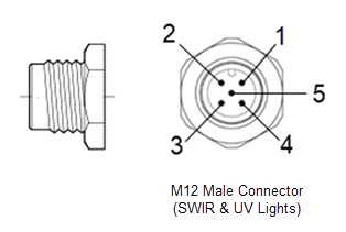
The current Basler Light uses the M12 5-pin connector model from CONEC (article no. 43-01013).
Info
The pin assignment of the light connector depends on whether the light is operated using its integrated controller (internal control) or an external controller. For details, refer to the relevant tables in the topics of the Controlling Basler Lights section:
Environmental Requirements#
| Temperature During Operation | 10–30 °C (50–86 °F) / 45 °C (113 °F)a |
| Humidity During Operation | 30–70 % |
-
For steady light operation without additional heat dissipation measures, a maximum of 30 °C (86 °F) is recommended. For a maximum of 45 °C (113 °F), heat dissipation measures are mandatory.
For flash light operation with a maximum 10 % duty cycle, a maximum of 45 °C (113 °F) is also permissible.