Operating Basler Lights with External Controller#
When using an external controller, the Basler light supports only the following control mode:
External Control Mode
In External Control Mode, an external LED controller directly regulates the current supplied to the light.
This topic describes the wiring and provides a sample circuit diagram for operating a Basler Light in external control mode, i.e., with an external LED controller. For other light control modes, refer to the Operating Basler Lights with Internal Controller topic.
Info
For electrical requirements of your light model, see the product topic of your light.
NOTICE – Setting up wrong current values in the controller may destroy the light.
Make sure that you configure the maximum current and duty cycle as described in the Electrical Specifications table of your light topic.
WARNING – Electric Shock Hazard
Connecting the Basler Light with the power supply turned on may result in electric shock, a fire, or destruction of the light. Make sure that the power source is turned off before connecting the Basler Light.
I/O Connector Pinout (External Control Mode)#
NOTICE – Connecting the pins incorrectly may destroy the light.
Make sure to connect the pins as described in the table below. Incorrect wiring may damage the light.
| Pin | External controller (without ILC) | External controller (with ILC) | Wire Colors for Cable M8, Axial Order Numbers: 2200000898, 2200000899, 2200000900 |
|---|---|---|---|
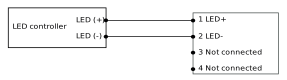
| 1 | Not connected | LED (+) | Brown |
| 2 | LED (+) | LED (-) | White |
| 3 (Signal) | Not connected | Not connected | Blue |
| 4 | Ground / LED (-) | Not connected | Black |
| 5 (only for M12) | Not used | Not used | - |
Pin 5 is only used on SWIR and UV lights which are equipped with a 5-pin M12 connector.
Info
For information about Basler Lights without intelligent light control (ILC), download the offline release version of the Basler Product Documentation by clicking here
Info
To find information about how to connect your Basler Light to your camera model, refer to your camera topic. You can find your camera topic in the Area Can Cameras and Line Scan Cameras section. The "Physical Interface" section in your camera topic describes the total number of I/O lines, the format of the lines (opto-coupled or GPIO), and the pin assignment.
Circuit Diagram#
Connecting a Light With ILC#
The following diagram shows a typical example circuit when using an external controller with a Basler Light with ILC (Intelligent Light Control).