Operating Basler Lights with Internal Controller#
Both light control modes use the same connector pinout and pin numbering. The function of the signal pin (pin 3) depends on the selected light device operation mode (continuous or strobe mode).
Info
The trigger control mode and the intelligent light control mode use the same connector pinout and pin numbering. In most cases, switching between the modes does not require rewiring. For information about in what cases a rewiring is required, see the Pin Assignment Changes in Light Revision 05 secton in the Basler Lights topic.
I/O Connector Pinout#
Info
To find information about how to connect your Basler Light to your camera model, refer to your camera topic. You can find your camera topic in the Area Can Cameras and Line Scan Cameras section. The "Physical Interface" section in your camera topic describes the total number of I/O lines, the format of the lines (opto-coupled or GPIO), and the pin assignment.
Connector Pin Numbering#

Info
Basler SWIR and Basler UV lights are equipped with an M12 5-pin connector, whereas all other Basler Lights use an M8 4-pin connector. Despite the different connector types, both use the same pin-out for installation.
The following connector models from CONEC are used:
- M12 5-pin connector (Basler SWIR and UV Lights): Article no. 43-01013
- M8 4-pin connector (all other Basler Lights): Article no. 42-01033
Trigger Control Mode#
In trigger control mode, the light reacts directly to an electrical trigger signal applied to the signal pin (pin 3). Depending on the wiring, the light can operate either continuously or in triggered strobe operation. Because no protocol communication is required, very short pulse durations and minimal latency can be achieved.
The trigger signal can be provided by a camera output, such as ExposureActive, UserOutput, or by another external trigger source.
The Trigger Control Mode section provides sample circuit diagrams and connection information for using the internal controller of a Basler Light in either continuous operation or triggered strobe operation.
Info
For electrical requirements of your light model, see the product topic of your light.
Pin Assignment (Trigger Control Mode)#
The pin assignment depends on whether you operate the light continuously or in strobe light operation.
NOTICE – Connecting the pins incorrectly may destroy the light.
Make sure that you connect the pins as described in the table below. If you connect them other than specified, you may damage the light.
| Pin | Continuous operation | Strobe mode (without ILC) | Strobe mode (with ILC) | Wire Colors for Cable M8, Axial Order Numbers: 2200000898, 2200000899, 2200000900 |
|---|---|---|---|---|
| 1 | 24 VDC | 24 VDC | 24 VDC | Brown |
| 2 | Not connected | Not connected | Not connected | White |
| 3 (Signal) | 24 VDC | Trigger source (5–24 VDC) | Trigger source (2.4–24 VDC) | Blue |
| 4 | Ground / LED (-) | Ground / LED (-) | Ground / LED (-) | Black |
| 5 | Not used | Not used | Not used | - |
Pin 5 is only used on SWIR and UV lights which are equipped with a 5-pin M12 connector.
Continuous Operation Diagram#
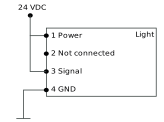
The following diagram shows a typical wiring diagram for a light operated in trigger control mode and continuous operation.
To operate the light continuously, connect the signal pin (pin 3) permanently to 24 VDC. This keeps the trigger input active and the LEDs remain on continuously.
Strobe Operation Diagram#
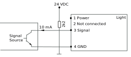
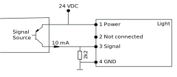
The following diagram shows a typical wiring diagram for a light operated in trigger control mode and strobe operation.
For strobe operation with a trigger from an NPN sinking (open-collector) output, the line will be held up with an pull-up resistor. If a Basler light with ILC (intelligent light control) is used, the pull-up resistor of the Basler camera's GPIO is sufficient. Otherwise, an external resistor (>=3V3 VDC) is required.
If the trigger signal is provided by a PNP sourcing output and the output is not a push-pull driver, ensure that the low level falls below 1 VDC by adding a pull-down resistor.
Intelligent Light Control Mode#
In the intelligent light control mode, a compatible camera controls the light via the SLP protocol. The camera manages triggering, timing, brightness settings, diagnostics, and monitoring functions through the Basler Light Control feature. Unlike the trigger control mode, no direct trigger signal is required for normal operation.
Info
For electrical requirements of your light model, see the product topic of your Basler Light.
Info
The intelligent light control mode is only available for special light variants. You need a Basler Light with intelligent light control (ILC) to use the intelligent light control mode. If in doubt, contact your local support.
Pin Assignment (Intelligent Light Control Mode)#
| Pin | Intelligent Light Control Mode (ILC Only) | Wire Colors for Cable M8, Axial Order Numbers: 2200000898, 2200000899, 2200000900 |
|---|---|---|
| 1 | 24 VDC | Brown |
| 2 | Not connected | White |
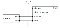
| 3 (Signal) | SLP signal (Line 3) | Blue |
| 4 | Ground | Black |
| 5 (only for M12) | Not used | - |
Circuit Diagram (Intelligent Light Control Mode)#
Switching Between Trigger Control and Intelligent Light Control Mode#
The trigger control mode and the intelligent light control mode use the same wiring. Therefore, you can switch between the two light control modes without modifying the physical connection.
Info
The overdrive functionality can be used in both intelligent light control (ILC) mode and trigger control mode. When switching between these modes, any configured overdrive settings remain active, eliminating the need to reconfigure the parameters.
While overdrive is available in both operating modes, trigger control mode allows higher flash frequencies to be achieved than the intelligent light control (ILC) mode, making it particularly suitable for high-speed applications that require rapid light pulses.
To ensure safe operation, integrated protection mechanisms continuously monitor the operating conditions and prevent LED damage, even when overdrive settings are applied.
To switch between trigger control mode and intelligent light control mode:
By default, a Basler Light starts in trigger control mode after power-up.
When a compatible camera detects the light (camera enumeration) and the Light Control feature is enabled, the light automatically switches to the intelligent light control mode. In this mode, the camera takes over control of all lighting functions.
To return to the trigger control mode:
- Disable the Light Control feature by setting the
BslLightDeviceOperationModeparameter toOff. - Keep line 3 (signal) at a low level for at least 10 ms.
To switch back to the intelligent light control mode:
- Enable the Light Control feature by setting the
BslLightDeviceOperationModeparameter toOnand re-enumerating the light devices.
Info
When switching back to intelligent light control (ILC) mode after using the overdrive functionality, the system reports a "DutyCycleOrPulseLength" error due to the underlying system design. This behavior is expected and does not indicate a malfunction. The error message can be safely ignored.
Info
When switching modes, brightness and overdrive settings are preserved and may still affect the light output after returning to trigger control mode.
Info
A device status monitoring functionality and individual light control in multi-light setups are available only in intelligent light control mode and are not supported in trigger control mode.
The status monitoring, using so-called heartbeat signals, allows the camera to monitor the operational status of the connected light device. The function detects communication failures and reports device status and error conditions provided by the light. This enables the camera application to identify issues such as disconnected, unavailable, or malfunctioning light devices and react accordingly.
The monitoring information is transmitted from the light device to the camera via the SLP communication channel.
Further Information#
- Light Control (ace U/L)
- Light Control for ace 2, boost R, and dart M cameras
- Basler SLP Strobe Controller
- Light Sync Cables
- Vision Sync Cables