Installation (Basler Standard Lights)#
Hardware#
Mounting#
All Basler Standard Lights have mounting holes that allow you to securely install the lights in your working environment. For information about which screws are required, refer to the Mechanical Specifications section in the product topic of your light.
Connecting External Controller and Light#
WARNING – Electric Shock Hazard
Connecting the Basler Standard Light with the power supply turned on may result in electric shock, a fire, or destruction of the light.
- Make sure that the power source is turned off before connecting the Basler Standard Light.
SLP Strobe Controller#
Basler recommends using the Basler SLP Strobe Controller to control your Basler Standard Light. For more information about how to connect the SLP Strobe Controller to your light, see the Basler SLP Strobe Controller documentation.
Operating the Light#
Info
To find information about how to connect your Basler Standard Light to your camera model, refer to your camera topic. You can find your camera topic in the Area and Line Scan Cameras section under "Models". The "Physical Interface" section in your camera topic describes the the total number of I/O lines, the format of the lines (opto-coupled or GPIO, and the pin assignment.
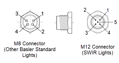
Connector Pin Numbering#

Info
The connector for SWIR lights differs from the connector of other Basler Standard Lights. SWIR lights are equipped with an M12 5-pin connector, while all other Basler Standard Lights are equipped with an M8 4-pin connector. Both connectors use the same pin-out for installation.
Internal Controller (Voltage Control Mode)#
The pin assignment of the light's connector differs depending on whether you want to operate the light continuously or in strobe mode. For more information, see the following tables.
Continuous Operation#
NOTICE – Connecting the pins incorrectly may destroy the light.
Make sure that you connect the pins as described in the table below. If you connect them other than specified, you may damage the light.
| Pin | Function |
|---|---|
| 1 | 24 VDC |
| 2 | Not connected |
| 3 | 24 VDC |
| 4 | Ground / LED (-) |
| 5 (only for M12) | Not used |
To operate the light continuously:
- Supply pin 1 and pin 3 with 24 VDC.
- Connect pin 4 to ground.
Strobe Mode#
NOTICE – Connecting the pins incorrectly may destroy the light.
Make sure that you connect the pins as described in the table below. If you connect them other than specified, you may damage the light.
| Pin | Function |
|---|---|
| 1 | 24 VDC |
| 2 | Not connected |
| 3 | Trigger source (5–24 VDC) |
| 4 | Ground / LED (-) |
| 5 (only for M12) | Not used |
External Controller (Current Control Mode)#
NOTICE – Connecting the pins incorrectly may destroy the light.
-
Pin 1: Don't connect an external LED controller to pin 1.
-
Pin 2: Only use pin 2 with an external LED controller.
| Pin | External Controller |
|---|---|
| 1 | Not connected |
| 2 | LED (+) |
| 3 | Not connected |
| 4 | Ground / LED (-) |
| 5 (only for M12) | Not used |
SLP Strobe Controller#
For more information about how to operate the light using the SLP Strobe Controller, see the Basler SLP Strobe Controller documentation.