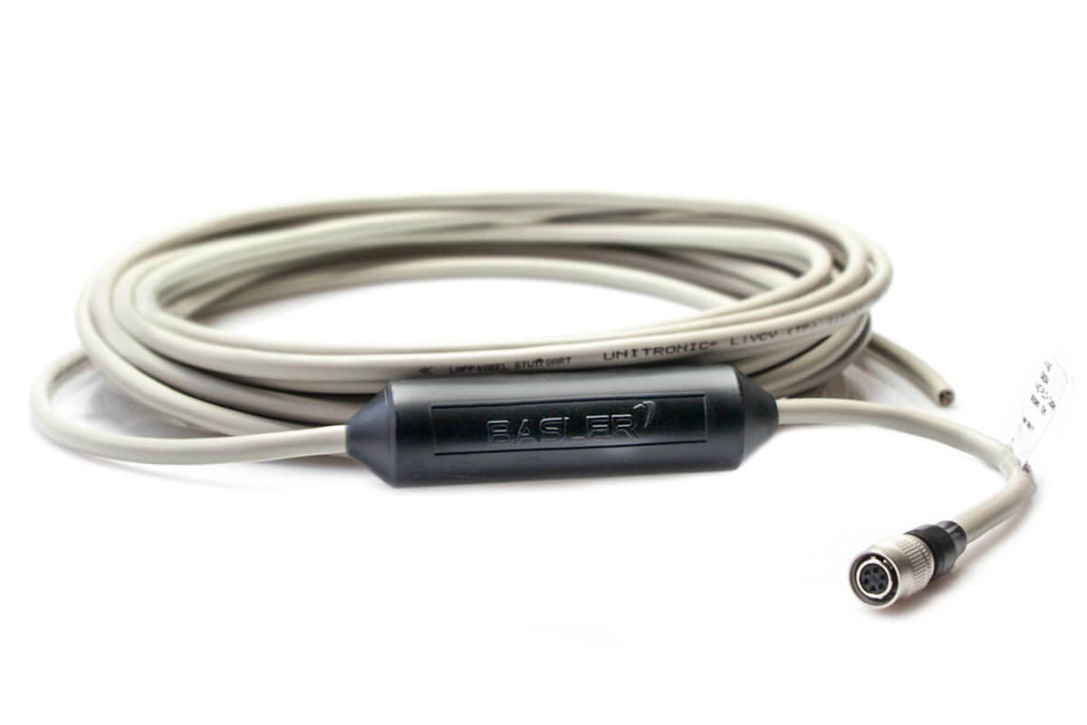
Basler Power-I/O PLC+ Cable 6p/open, P#

Introduction#
The Power-I/O-PLC+ cables with Hirose 6-pin connector and open end feature an integrated PLC+ electronic board.
The key feature of this board is that it is able to adjust input voltage levels coming from PLC devices (up to 24 V) to the TTL voltage levels required by the camera (0 to 5 V). The table below contrasts these different voltage levels.
In addition, the PLC+ electronic board protects the power supply of the camera as well as the input and output lines of the camera against the following:
- Reverse polarity
- Turn-on voltage spikes
- Positive or negative overvoltage spikes
The cables also offer protection of the signal transmission as well as the power supply against EMI and ESD. This is achieved by means of twisted pair cables in which each pair of wires carries just one signal: one wire carries the signal itself and the other is the signal's own return conductor.
| Camera I/O Signal Voltage | PLC+ Cable Input Voltage | Description |
|---|---|---|
| Max. 24 VDC | Max. 24 VDC + 10 % | Operating voltage limit. |
| 0–1.4 VDC | 0–8.4 VDC | Voltage indicates a logical 0. |
| >1.4–2.2 VDC | >8.4–10.4 VDC | Logical state is undefined. |
| >2.2 VDC | >10.4 VDC | Voltage indicates a logical 1. |
Technical Data#
Info
The cable is suitable for the following camera models:
- ace GigE
- Only suitable for use with opto-coupled IO lines.
- ace USB 3.0
- Only suitable for use with opto-coupled IO lines.
- Take additional safety measures.
| Order Number | Cable Length |
|---|---|
| 2000034084 | 10 m |
Cable Drawing#
CAUTION – Personal Injury Hazard
Personal injury hazard and risk of damage to camera in case of short circuits (applies to GigE cameras only)
Short circuits may cause an extreme rise in temperature of the camera's housing. This may damage the camera and may also lead to personal injuries, e.g., burns if touching the housing. In the worst case, the overheating may cause a fire. In order to prevent that, you should take additional measures to limit the current flowing through each individual wire during a short circuit. The maximum current allowed is 2 A. There are two ways how to do this:
- Using a fuse
- Using a limited power supply
Wiring Information#
Info
(x) means that the wire is connected internally to pin x.
| Pin Number | Wire Color | ace GigE | ace USB 3.0 |
|---|---|---|---|
| 1 | Brown | Camera Power | Used for providing additional safety measures. |
| 2 | Pink | Opto-isolated IN (Line1) | Opto-isolated IN (Line1) |
| (5) | Gray | Opto-isolated IN Ground (Line1) | Opto-isolated IN Ground (Line1) |
| 4 | Yellow | Opto-isolated OUT (Out1) | Opto-isolated OUT (Out1) |
| (5) | Green | Opto-isolated OUT Ground (Out1) | Opto-isolated OUT Ground (Out1) |
| 6 | White | Camera Power Ground | Used for providing additional safety measures. |
Info
Safety Measures When Using Cable with ace USB 3.0 Cameras
Make an electrical connection between the brown and the white wire, e.g., by soldering. Insulate the connection from the other wires. See the following figure for details.
Physical Specifications#
| Camera-side Connector | Hirose 6 pin [HR10A-7P-6S (73)] |
| Host-side Connector | None, open end |
| Cable Cross-section | 3 x 2 x 0.14 mm² (close to AWG 26) |
| Cable Diameter | 5.8 mm |
| Wire Insulation | PVC |
| Outer Jacket | PVC |
| Minimum Bending Radius | 34.8 mm (6 x cable diameter), fixed installation |
| Maximum Bending Cycles | None (fixed installation only) |
| Suitable for Drag Chain Applications | No |
| Suitable for Robotics Applications | No |
Electrical Specifications#
| Nominal Operating Voltage | See camera documentation for the power requirements of your camera. |
| Maximum Operating Voltage | See camera documentation for the power requirements of your camera. |
| Wire Resistance | ≤142 Ω/km |
Environmental Specifications#
| Operating Temperature Range | -25–80 °C, not moving |
Plug Specifications#
| Durability | >1000 mating cycles |
| Contact Resistance | 10 mΩ max. |
| Contact Plating | Silver |
| Protection Rating | IP40 |
| Plug Insulation Material | Polyamide/PBT |
General Information#
| Conformity | CE (includes RoHS) Certificates for your cable For more information, see the Compliance section of the Basler website. |
| Warranty | 3 years |
Read the topic about your camera model before connecting the cable to the camera. You can find your camera topic in the Area and Line Scan Cameras section under "Models".