GigE Line Scan Use Case Descriptions and Diagrams
This topic describes common use cases for Basler GigE and 5GigE line scan cameras and how to configure these cameras for the given use cases.
The use cases in this topic are intended to help you in developing an initial understanding of how triggers and parameters interact.
Info
- The camera provides multiple trigger functions, e.g., Line Start trigger or Frame Active trigger, that can be set by the Trigger Selector parameter. All parameters related to the trigger configuration that aren't indicated in the following use case examples, are assumed to remain at their factory default values.
- For further information about triggering, see the Triggered Image Acquisition and Aquisition Timing Information topics.
- The Features section lists all camera features, e.g., Line Timeout and Spatial Correction, and provides detailed information about how to use and configure them.
Info
For the sake of simplicity, the frame height in the following use case examples is set to only a few lines (e.g., 3 lines). However, for real-world applications, Basler recommends a frame height of at least 100 to 1000 lines per frame.
Info
- GigE Vision line scan cameras combine multiple lines to a larger frame. This can greatly reduce the processing load for the recipient (e.g., host computer, transport layer).
- If an acquisition stop command is issued when not all lines of the current frame are acquired yet, a partial frame will be transmitted.
Use Case 1: Endless Stream of Objects or Material
This is the most basic way of using a GigE line scan camera. The camera transmits a continuous stream of image frames. The host computer can combine multiple frames to build a larger image or process each frame on its own.
The objects or the endless material are moved through the camera's field of view. The camera acquires the first line. Afterwards, the object or the material is moved by one line and the camera acquires the next line, and so on.
The following sections describe two variants of use case 1:
Case 1 a: Objects Moving at a Constant Speed
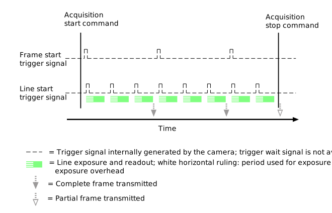
When objects are free-falling, e.g., when sorting rice, cotton, or material for recycling, these objects move at a predictable speed and the camera can be set to a fixed line rate. No triggers are necessary to acquire geometrically correct images.
The following steps are required to configure the camera for this use case:
| Action | Parameter Example |
- Specify the height of the frame.
This depends on the size of the objects. Calculate how many lines per frame you need to capture an object.
| - Set the
Height parameter to 3.
|
- Enable the acquisition line rate control.
You have to control the acquisition line rate in order to synchronize the camera with the speed at which your objects move.
| - Set the
AcquisitionLineRateEnable parameter to true.
|
- Slow down the line rate to the desired speed.
The acquisition line rate must be synchronized with the speed at which your objects move.
| - Set the
AcquisitionLineRate parameter to 10 kHz.
|
- Enable the Continuous acquisition mode.
In Continuous acquisition mode, the camera continuously acquires and transfers images.
Note: This feature is not available via the pylon Viewer feature tree. Instead, use the Continuous Shot button in the toolbar of the pylon Viewer.
| - Set the
AcquisitionMode parameter to Continuous.
|
This diagram illustrates the configuration:
Case 1 b: Endless Material Moved by Rollers at Variable Speed
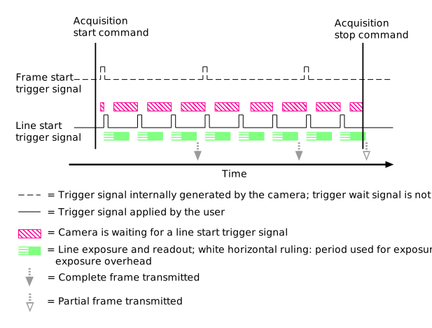
Endless material is often moved by and over rollers. Load changes and vibrations cause the transport speed to vary. This fluctuation in speed can be compensated when a shaft encoder is used to generate a line trigger each time the material moves forward by a certain distance.
In the following example, the shaft encoder signal is connected to input line 2. The shaft encoder is set up to generate one encoder pulse per line.
The following steps are required to configure the camera for this use case:
| Action | Parameter Example |
- Specify the height of the frame.
This depends on the size of the objects. Calculate how many lines per frame you need to capture an object.
| - Set the
Height parameter to 3.
|
- Configure the line start trigger.
You have to enable the trigger and define which signal and which signal transition should be used for triggering the line start trigger.
| - Set the
TriggerSelector parameter to LineStart. - Set the
TriggerMode parameter to On. - Set the
TriggerActivation parameter to RisingEdge. - Set the
TriggerSource parameter to Line2.
|
- Enable the Continuous acquisition mode.
In Continuous acquisition mode, the camera continuously acquires and transfers images.
Note: This feature is not available via the pylon Viewer feature tree. Instead, use the Continuous Shot button in the toolbar of the pylon Viewer.
| - Set the
AcquisitionMode parameter to Continuous.
|
This diagram illustrates the configuration:
Use Case 2: Individual Objects on a Conveyor Belt
When inspecting objects on a moving conveyor belt, it is often desirable to receive one image per object. This facilitates image processing and avoids the waste of processing resources. In this setup, the system usually provides an object trigger that indicates the arrival of the next object. The object trigger can be generated, e.g., by a light barrier or by a PLC (programmable logic control) unit.
The conveyor belt speed may fluctuate. It is therefore often advisable to use a shaft encoder to synchronize the line trigger to the mechanical movement of the belt. The following examples assume that a line trigger is used.
The following sections describe four variants of use case 2:
Case 2 a: One Frame per Object
When the objects are small enough so that each fits in one frame, the object trigger can be used as a direct frame trigger.
For information about the possible number of lines per frame, see the information about line scan cameras in the Image ROI topic.
The following steps are required to configure the camera for this use case:
| Action | Parameter Example |
- Specify the height of the frame.
This depends on the size of the objects. Calculate how many lines per frame you need to capture an object.
| - Set the
Height parameter to 3.
|
- Configure the frame start trigger.
You have to enable the trigger and define which signal and which signal transition should be used for triggering the frame start trigger.
| - Set the
TriggerSelector parameter to FrameStart. - Set the
TriggerMode parameter to On. - Set the
TriggerActivation parameter to RisingEdge. - Set the
TriggerSource parameter to Line1.
|
- Configure the line start trigger.
You have to enable the trigger and define which signal and which signal transition should be used for triggering the line start trigger.
| - Set the
TriggerSelector parameter to LineStart. - Set the
TriggerMode parameter to On. - Set the
TriggerActivation parameter to RisingEdge. - Set the
TriggerSource parameter to Line2.
|
- Enable the Continuous acquisition mode.
In Continuous acquisition mode, the camera continuously acquires and transfers images.
Note: This feature is not available via the pylon Viewer feature tree. Instead, use the Continuous Shot button in the toolbar of the pylon Viewer.
| - Set the
AcquisitionMode parameter to Continuous.
|
This diagram illustrates the configuration:
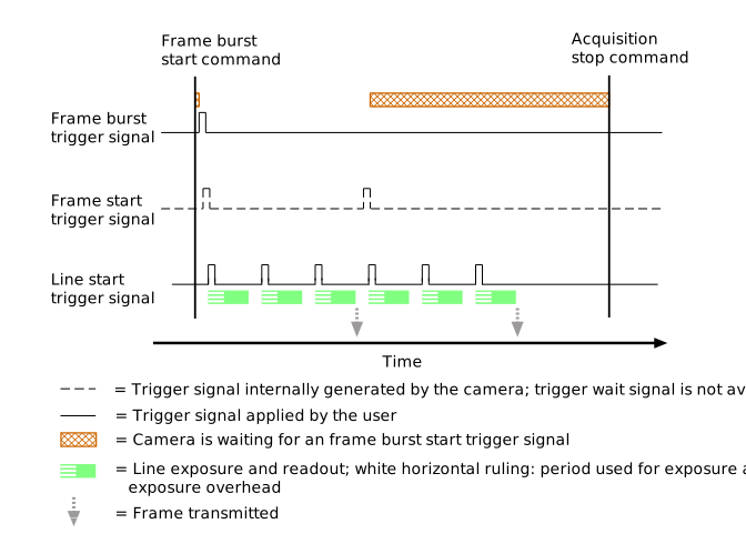
Case 2 b: Multiple Frames per Object
When the objects are too large to fit in one frame, a frame burst trigger can be used to trigger multiple frames for each individual object trigger. The image processing application may combine all frames of a frame burst into one image.
The following steps are required to configure the camera for this use case:
| Action | Parameter Example |
- Specify the height of the frame.
This depends on the size of the objects. Calculate how many lines per frame you need to capture an object.
| - Set the
Height parameter to 3.
|
- Set the number of frames to acquire for each frame burst.
| - Set the
AcquisitionBurstFrameCount parameter to 2.
|
- Configure the frame burst start trigger.
You have to enable the trigger and define which signal and which signal transition should be used for triggering the frame burst start trigger.
| - Set the
TriggerSelector parameter to FrameBurstStart. - Set the
TriggerMode parameter to On. - Set the
TriggerActivation parameter to RisingEdge. - Set the
TriggerSource parameter to Line1.
|
- Configure the line start trigger.
You have to enable the trigger and define which signal and which signal transition should be used for triggering the line start trigger.
| - Set the
TriggerSelector parameter to LineStart. - Set the
TriggerMode parameter to On. - Set the
TriggerActivation parameter to RisingEdge. - Set the
TriggerSource parameter to Line2.
|
- Enable the Continuous acquisition mode.
In Continuous acquisition mode, the camera continuously acquires and transfers images.
Note: This feature is not available via the pylon Viewer feature tree. Instead, use the Continuous Shot button in the toolbar of the pylon Viewer.
| - Set the
AcquisitionMode parameter to Continuous.
|
This diagram illustrates the configuration:
Case 2 c: Varying Number of Frames per Object
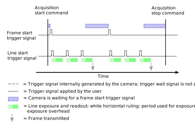
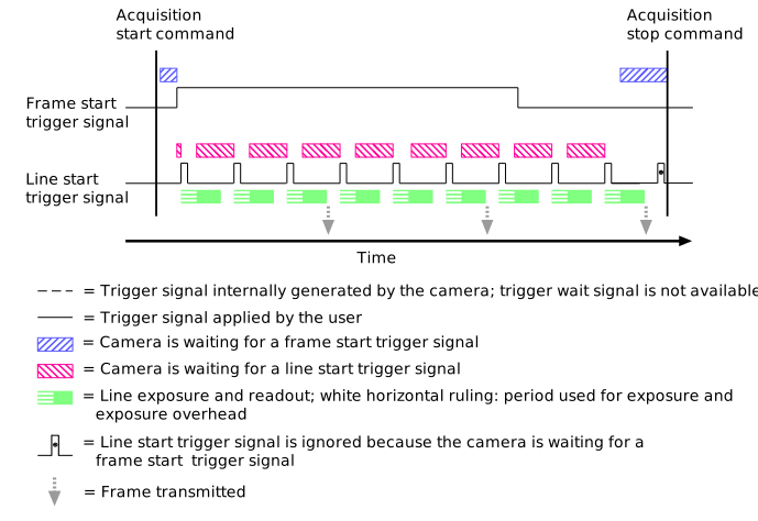
When a mix of objects of varying sizes is inspected on the same conveyor belt, the frame start trigger can be used to acquire exactly the required number of frames for each object. The frame trigger signal should be generated by a presence detector, e.g., a light barrier, to ensure the signal is active whenever the object is in the camera's field of view.
The following steps are required to configure the camera for this use case:
| Action | Parameter Example |
- Specify the height of the frame.
This depends on the size of the objects. Calculate how many lines per frame you need to capture an object.
| - Set the
Height parameter to 3.
|
- Configure the frame start trigger.
You have to enable the trigger and define which signal and which signal transition should be used for triggering the frame start trigger.
Set the trigger to act on a high level of the presence detector's output signal. This results in a sequence of frame triggers issued while the trigger signal is active.
| - Set the
TriggerSelector parameter to FrameStart. - Set the
TriggerMode parameter to On. - Set the
TriggerActivation parameter to LevelHigh. - Set the
TriggerSource parameter to Line1.
|
- Configure the line start trigger.
You have to enable the trigger and define which signal and which signal transition should be used for triggering the line start trigger.
| - Set the
TriggerSelector parameter to LineStart. - Set the
TriggerMode parameter to On. - Set the
TriggerActivation parameter to RisingEdge. - Set the
TriggerSource parameter to Line2.
|
- Enable the Continuous acquisition mode.
In Continuous acquisition mode, the camera continuously acquires and transfers images.
Note: This feature is not available via the pylon Viewer feature tree. Instead, use the Continuous Shot button in the toolbar of the pylon Viewer.
| - Set the
AcquisitionMode parameter to Continuous.
|
This diagram illustrates the configuration:
Case 2 d: Variable Size of Frames per Object
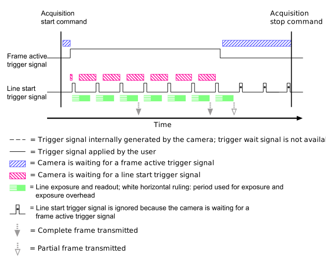
When the gap between objects on a conveyor belt is smaller than a frame, the frame active trigger can be used to end the frame immediately behind the object. This prepares the camera for the next trigger as quickly as possible and it avoids transmitting unnecessary data.
The following steps are required to configure the camera for this use case:
| Action | Parameter Example |
- Specify the height of the frame.
This depends on the size of the objects. Calculate how many lines per frame you need to capture an object.
| - Set the
Height parameter to 3.
|
- Configure the frame active trigger.
You have to enable the trigger and define which signal and which signal transition should be used for triggering the frame active trigger.
Set the trigger to act on a high level of the presence detector's output signal. This results in a sequence of one or multiple frame triggers issued while the trigger signal is active, but the frame will end immediately with the falling edge of the trigger signal.
| - Set the
TriggerSelector parameter to FrameActive. - Set the
TriggerMode parameter to On. - Set the
TriggerActivation parameter to LevelHigh. - Set the
TriggerSource parameter to Line1.
|
- Configure the line start trigger.
You have to enable the trigger and define which signal and which signal transition should be used for triggering the line start trigger.
| - Set the
TriggerSelector parameter to LineStart. - Set the
TriggerMode parameter to On. - Set the
TriggerActivation parameter to RisingEdge. - Set the
TriggerSource parameter to Line2.
|
- Enable the Continuous acquisition mode.
In Continuous acquisition mode, the camera continuously acquires and transfers images.
Note: This feature is not available via the pylon Viewer feature tree. Instead, use the Continuous Shot button in the toolbar of the pylon Viewer.
| - Set the
AcquisitionMode parameter to Continuous.
|
This diagram illustrates the configuration:
Use Case 3: Using the Chunk Mode for Identifying Frames
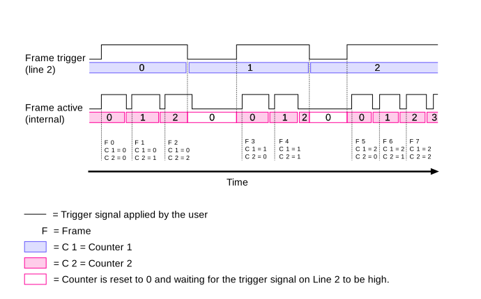
When a camera is configured to acquire a variable number of frames per object as described for use cases 2 b or 2 d, it is not clear for the application where objects begin and end. The Data Chunks feature, in combination with the Counter feature, can be used to tag frames as belonging to the same object trigger, thus making it unnecessary to spend processing power on grouping frames together.
The following use case is an example of how to configure the counters and the data chunks for use case 2 c. The counters can be used individually or together.
The following steps are required to configure the camera for this use case:
| Action | Parameter Example |
- Set the first counter to increment after each incoming frame start trigger.
You have to select the frame trigger signal for line 2 as the signal source for the counter event (i.e. for incrementing). Also, you have to select the end of the active frame trigger signal to increment the counter.
| - Set the
CounterSelector parameter to Counter1. - Set the
CounterEventSource parameter to Line2. - Set the
CounterEventActivation parameter to FallingEdge.
|
- Set the second counter to count the number of frames while the frame trigger is continuously active.
The counter should only count while line 2 is active.
The counter should increment at the end of each frame.
The counter should be reset when line 2 becomes inactive.
| - Set the
CounterSelector parameter to Counter2. - Set the
CounterTriggerSource parameter to Line2. - Set the
CounterTriggerActivation parameter to LevelHigh. - Set the
CounterEventSource parameter to FrameActive. - Set the
CounterEventActivation parameter to FallingEdge. - Set the
CounterResetSource parameter to Line2. - Set the
CounterResetActivation parameter to Falling Edge.
|
- Activate the transmission of counter values.
| - Set the
ChunkModeActive parameter to true. - Set the
ChunkSelector parameter to CounterValue. - Set the
ChunkEnable parameter to true.
|
This diagram illustrates the configuration: