Mounting Instructions#
ace 2 and racer 2 S Cameras#
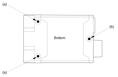
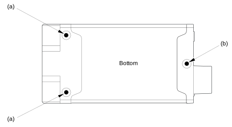
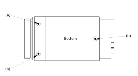
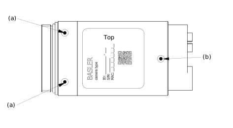
When mounting ace 2 and racer 2 S cameras in your system, you must tighten the screws in a certain order. This ensures optimum alignment of the camera.
Tightening the M3 Screws#
To tighten the M3 screws:
- Tighten the screws for the mounting screw holes (a) in the figure below.
- Tighten the screw for the mounting screw hole (b) in the figure below.
USB 3.0, CoaXPress, and GMSL Cameras#
GigE Cameras#
GigE Cameras (IP67 Only)#
Tightening the Cable Connectors (IP67 Cameras Only)#
NOTICE – Basler ace 2 IP67 cameras: Incorrect tightening torque may damage the connectors or compromise IP67 protection.
Tighten the M8 I/O cable connector, the M12 Ethernet cable connector, and the M8 blanking plug only with a torque wrench that can apply and control the specified torques.
Apply the following tightening torques:
- M8 I/O cable connector: 25–40 Ncm
- M12 Ethernet cable connector: 40–60 Ncm
- M8 blanking plug: 20 Ncm (if you reinsert the blanking plug that is supplied with the camera)
ace Classic/U/L USB 3.0 Cameras#
When mounting ace USB 3.0 cameras in your system, you must tighten the screws in a certain order. This ensures optimum alignment of the camera.
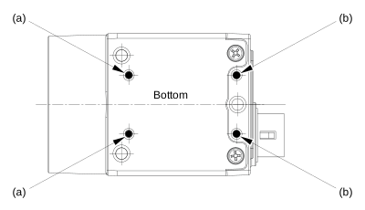
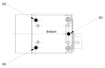
Depending on whether you use M2 or M3 screws, the order for tightening the screws varies.
Info
- Basler ace L USB 3.0 cameras use M3 screws of different lengths. These cameras can't be mounted using M2 screws.
- The following illustrations show cameras with C-mounts. The mounting instructions apply, however, also to cameras with CS-mounts.
Using M2 Screws#
To tighten the M2 screws:
- Tighten the screws for the mounting screw holes (a) in the figure below.
- Tighten the screws for the mounting screw holes (b) in the figure below.
Using M3 Screws#
To tighten the M3 screws:
- Tighten the screws for the mounting screw holes (a) in the figure below.
- Tighten the screw for the mounting screw hole (b) in the figure below.
dart Cameras#
dart Classic/R/E#
When mounting the bare board variant of dart cameras in your system, make sure that the head diameter of the screws used for mounting doesn't exceed 4.6 mm.
Otherwise, mounting the camera may damage components on the board.
dart M Camera Modules#
Mechanical Requirements#
When mounting the dart M camera modules in your system, observe the following points to make sure that components won't be damaged:
- The head diameter of the screws used for mounting mustn't exceed 4.5 mm.
- Mount the screws within a torque range of 0.2–0.25 Nm (maximum torque: 0.25 Nm).
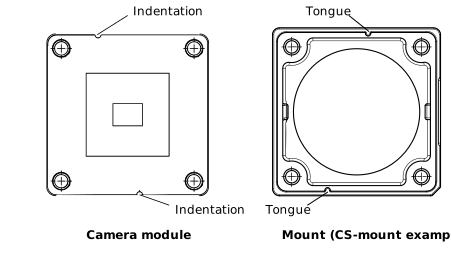
- Make sure that the tongues of the mount fit into the correct indentations of the camera module (see figure below). If necessary, turn the mount until the tongues match the camera module's indentations.
FFC Connector#
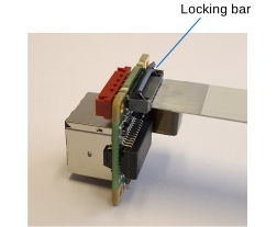
If you want to disconnect the flexible flat cable from the FFC connector, make sure to unlock the FFC connector by flipping the locking bar up before removing the cable.
Providing Strain Relief for the RJ45 Connector#
NOTICE – Insufficient strain relief may damage the dart M interface board or the dart M GigE switch.
The RJ45 connector for the network connection is mounted as an SMD component. It is not designed to absorb mechanical loads from the attached cable. Without adequate strain relief, mechanical forces acting on the network cable can pull the RJ45 connector or its solder pads off the interface board or the GigE switch, resulting in permanent hardware damage and loss of the network connection.
To avoid mechanical stress, provide suitable strain relief for the network cable:
- Secure the cable near the Ethernet/RJ45 connector.
- Prevent tensile, bending, and torsional forces from acting on the connector.
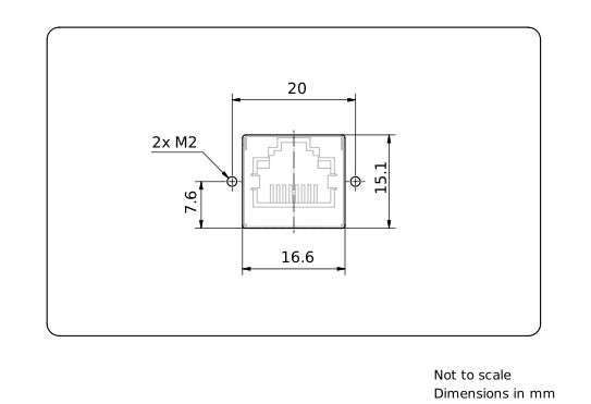
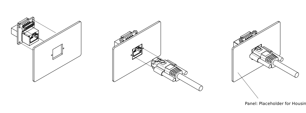
- Mount the RJ45 connector to a housing, panel, or similar rigid structure that absorbs mechanical loads and prevents stress on the connector. The following drawing shows a panel mount example for the dart M interface board. The panel may also form part of a housing.
Observe the relevant dimensions indicated in the figure below the Notice box.
Recommended Panel Cut-Out and M2 Mounting Hole Locations