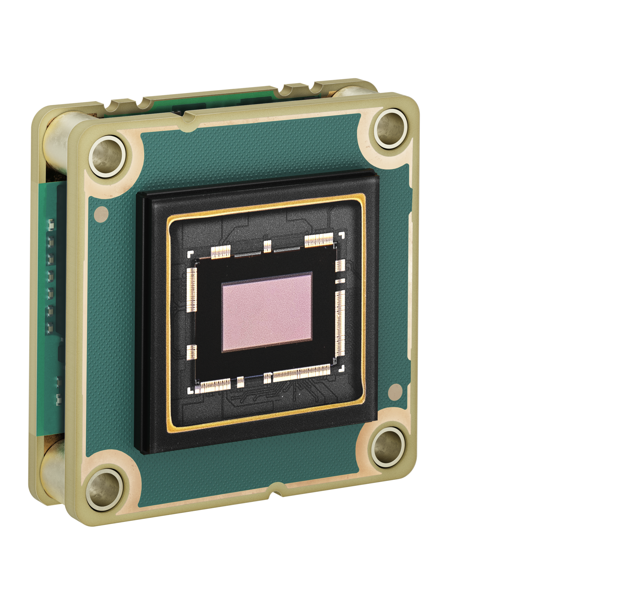
dmA2840-14gc#

Specifications#
General Specifications#
| dmA2840-14gc | |
|---|---|
| Resolution (H x V Pixels) | 2856 x 2848 (full resolution) 2840 x 2840 (default resolution) |
| Resolution | 8 MP |
| Sensor Type | Sony IMX546-AAQJ-C Progressive scan CMOS Global shutter |
| Sensor Format | 2/3" |
| Effective Sensor Diagonal | 11.1 mm |
| Pixel Size (H x V) | 2.74 x 2.74 µm |
| Frame Rate (at Default Settings) | 12.7 fps 14.5 fps (with Bandwidth Reserve mode set to Performance and packet size set to 4000) See also the Basler Frame Rate Calculator (baslerweb.com). |
| Product Family | dart M |
| Mono / Color | Color |
| Image Data Interface | Fast Ethernet (100 Mbit/s) Gigabit Ethernet (1000 Mbit/s) |
| Pixel Formats | See Pixel Format. |
| Synchronization | Via hardware trigger Via software trigger Via free run |
| Exposure Time Control | Via hardware trigger Programmable via the camera API |
| Camera Power Requirements | ≈3.0 W (typical) @ 5 VDC |
| I/O Lines | 1 general purpose input line 1 general purpose output line When using a Basler dart M Interface Board or a dart M GigE Switch: 1 opto-coupled input line 1 general purpose output line 1 general purpose I/O (GPIO) line |
| Lens Mount | C-mount, S-mount, and CS-mount available as accessories |
| Size (L x W x H) | 27.3 x 27.3 x 13.9 mm |
| Weight | <14 g |
| Conformity | CE (includes RoHS), UKCA, EAC, FCC, KC, GenICam, GigE Vision, REACH Certificates for your camera model For more information, see the Compliance section of the Basler website. |
| Software | Basler pylon Software Suite (version 6.0 or higher) Available for Windows, Linux x86, Linux ARM, macOS, and Android |
| Accessories | dart M GigE Switches or dart M Interface Boards dart Camera Mounts dart M Screw Kit for Mount Attachment dart Flexible Flat Cables dart I/O Cable Heat Sink for dart See also the Suitable Products section on the Basler website. |
| Availability and Pricing | See the product page on the Basler website. |
Spectral Response#
The spectral response curve excludes lens characteristics, light source characteristics, and IR cut filter characteristics.
Mechanical Specifications#
Dimensions and Mounting Points#
– > Download the CAD/technical drawing for your Basler Camera.
Info
If you use a camera mount, different dimensions apply. For more information, see dart M Camera Mounts.
The top and bottom of the image sensor, as shown in the image above, correspond to the top and bottom of the delivered image (see below).
Mounting Instructions#
→ See Mounting Instructions.
Stress Test Results#
→ See Stress Test Results.
Requirements#
Environmental Requirements#
Temperature and Humidity#
| Description | Temperature |
|---|---|
| Device temperature during operation | 0–75 °C (32–167 °F)a |
| Device temperature during storage | -20–80 °C (-4–176 °F) |
| Humidity | 20–80 %, relative, non-condensing |
-
Temperature measured at the temperature measurement point, i.e., at the hottest point on the board. This point is significantly hotter than the other parts on the board.
Heat Dissipation#
CAUTION – Temperatures outside of the specified range may cause burns or lead to a camera shutdown.
Operating the camera module at temperatures outside of the range given in the camera specification causes the following problems:
- The camera module gets hot and may cause burns when touching it.
- Operating the camera module without heat dissipation may lead to a shutdown of the camera module in order to protect its electrical components.
- The camera module's lifetime decreases.
Ensure sufficient heat dissipation.
→ See Providing Heat Dissipation.
→ See the How to Effectively Provide Heat Dissipation for dart M Camera Modules application note.
Electrical Requirements#
For information about the camera power requirements, see the General Specifications table above.
→ If you want to connect the camera module to Basler hardware, see dart M Interface Boards or dart M GigE Switch.
→ If you want to connect the camera module to custom hardware, see dart M Interface Description.
Physical Interface#
FFC Connector#
The FFC connector provides an interface to a dart M Interface Board or to a dart M GigE Switch via the dart M FFC cable.
You can also connect custom hardware. For more information, see dart M Interface Description.
I/O Pinout#
→ If you want to connect the camera module to Basler hardware, see dart M Interface Boards or dart M GigE Switch.
→ If you want to connect the camera module to custom hardware, see dart M Interface Description.
Precautions#
→ See Safety Instructions (dart Cameras).
Installation#
→ See Camera Installation.
Features#
→ See Features.