TDI (Time Delay Integration)#
TDI increases the light sensitivity and produces brighter images with a wider dynamic range, which makes it ideal for use in low-light conditions.
Info
This feature is only available on Basler racer 2 XL and racer 2 L mono cameras.
Using the Feature#
The implementation of this feature varies depending on the camera:
racer 2 XL Cameras#
racer 2 XL cameras are equipped with a TDI sensor. A TDI sensor consists of multiple rows of pixels, called stages, which are arranged in an array.
When an object moves across the sensor's field of view, its image is projected from the exposure area of the first stage to the exposure area of the last stage. The stages aren't exposed individually stage after stage, but are exposed as an entire block. So, the sensor exposes the same object at every stage and accumulates and transfers the charges until they reach the readout line.
The following illustration visualizes the charge transfer within a sensor with four stages.
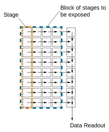
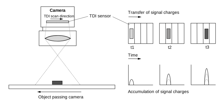
The charge transfer from one stage to the next must be in exact synchronization with the movement of the object. This ensures continuous exposure and charge integration. The exposure of the object lasts as long as it is in the field of view of the camera. The more stages are used, the longer the effective exposure time and integration time.
The following illustration shows the field of view of a TDI sensor and its charge shifting principle:
Number Of Stages#
The number of stages determines how often the charge is accumulated and shifted from one stage to the next until reaching the last stage. The higher the number of stages, the higher the image sensitivity. For example, if the number of stages is 256, the camera will acquire images with a 256 times higher sensitivity. The number of stages also affects the resulting exposure time.
The sensor can be set to work with different numbers of stages, e.g., 4 stages or up to 256 stages. The numbers of stages available depend on the sensor used.
To set the number of stages, set the BslTDINumberOfStages parameter value to, e.g., Stages4 or Stages256.
Info
In Area sensor acquisition mode, the number of stages determines the image height. For example, with a number of stages set to 128, the r2T16416-500cm camera would acquire 16416 x 128 "area" images in Area sensor acquisition mode.
Scan Direction#
The TDI sensor's scan direction must be synchronized with the movement of the object passing the camera. The scan direction must be the same direction as the object is moving to ensure continuous exposure and charge integration.
Info
The description of how to set the scan direction assumes that you use a lens on the camera. The lens inverts the image.
To set the scan direction, set the BslTDIScanDirection parameter to one of the following values:
Forward: The object passing the field of view of the sensor is scanned in the forward scan direction. It passes first the bottom and then the top of the camera.Reverse: The object passing the field of view of the sensor is scanned in the reverse scan direction. It passes first the top and then the bottom of the camera.
Resulting Exposure Time#
In TDI sensor acquisition mode, the exposure time isn't set via the ExposureTime parameter. Instead, it results from two acquisition parameters:
- Number of stages: Defines how long the object remains in the sensor's field of view while charges are accumulated and shifted.
- Line rate: Defines how quickly charges are shifted from one stage to the next. It also determines the integration time per individual stage.
Both parameters together determine the total exposure time:
$$ \text{Exposure time} = \frac{\text{Number of stages}}{\text{Line rate}} $$
The following table shows example exposure times at a fixed line rate of 500 kHz and different numbers of stages:
| Number of Stages | Line Rate [kHz] | Exposure Time [µs] |
|---|---|---|
| 4 | 500 | 8 |
| 64 | 500 | 128 |
| 128 | 500 | 256 |
| 256 | 500 | 512 |
The following table shows example exposure times at a fixed number of 128 stages and different line rates up to the maximum of 500 kHz:
| Line Rate [kHz] | Number of Stages | Exposure Time [µs] |
|---|---|---|
| 100 | 128 | 1280 |
| 200 | 128 | 640 |
| 400 | 128 | 320 |
| 500 | 128 | 256 |
Because the number of stages and the line rate both influence the exposure time, they also affect image brightness, provided that triggering is correctly synchronized with the movement of the object and that the pixel saturation limits are respected:
- A higher number of stages increases the exposure time and therefore results in more accumulated charge. The image will appear brighter.
- A lower number of stages decreases the exposure time and therefore results in less accumulated charge. The image will appear darker.
- A higher line rate decreases the exposure time per stage and therefore results in less accumulated charge. The image will appear darker.
- A lower line rate increases the exposure time per stage and therefore results in more accumulated charge. The image will appear brighter.
Configuring racer 2 XL Cameras for TDI#
To configure the racer 2 XL camera for TDI:
- Set the
BslSensorAcquisitionModeparameter toTDISingleLine. The sensor uses one readout line. - Depending on your system setup, set the
BslTDIScanDirectionparameter to, e.g.,Forward. - Set the
BslTDINumberOfStagesparameter to, e.g., 128.
Info
- Make sure that the sensor's readout procedure is exactly synchronized with the speed and direction of the object's movement. For testing purposes, change the acquisition line rate accordingly. This also affects the resulting exposure time.
- When re-triggering after a trigger pause, at least the first n readout lines must be considered invalid, with n representing the minimum number of stages.
racer 2 L Mono Cameras#
racer 2 L mono cameras are equipped with a multi-line sensor, i.e., a dual-line or quad-line sensor. Each pixel line of the sensor can be set to be exposed with a different exposure time. Whenever an acquisition is triggered, all pixel lines of the sensor are exposed simultaneously. For a single exposure, each line in the sensor acquires a different area on the object since each line has a different field of view on any object passing the camera.
The following illustration shows the field of view of a mono quad line sensor.

In this case, the data from four different acquisitions must be buffered and combined to get the full information for a certain area on an object. This is done by spatial correction. The data of the last line of the current exposure is combined with the data of the previous lines, taken from exposures in the past.
Using the Line Combination Mode, you can finally specify the way the pixel values of the individual lines should be combined to get your HDR image.
Line Combination Mode#
The line combination mode allows you to define whether the pixel values of the combined sensor lines are summed or averaged. You can set the BslLineCombinationMode parameter to one of the following values:
Off: Line combination is disabled.TDISum: The pixel values of the combined sensor lines are summed. This increases the camera's response to light and the signal-to-noise ratio.TDIAverage: The pixel values of the combined sensor lines are averaged. This increases the signal-to-noise ratio without affecting the camera's response to light.
Configuring racer 2 L Mono Cameras for TDI#
To configure the racer 2 L mono camera for TDI:
- Set the sensor acquisition mode to Dual or Quad Line image acquisition:
Set theBslSensorAcquisitionModeparameter toDualLineorQuadLinedepending on whether you want to use two or four lines for TDI. -
Specify the exposure time for each line (stage):
- Set the
ExposureTimeModeparameter toIndividual. - Set the
ExposureTimeSelectorparameter toStage1. - Set the
ExposureTimeparameter to the desired exposure time in microseconds.
Note: You can find the minimum and maximum exposure time values of your camera model in the Specifics section of the Exposure Time topic. - Repeat steps b and c for the other stages.
- Set the
-
Specify the spatial correction stride to determine the starting line and direction of spatial correction:
Set theBslSpatialCorrectionStrideparameter to, e.g., 2. - Set the line combination mode to determine whether the sensor pixel values of the combined lines are summed or averaged:
Set theBslLineCombinationModeparameter to, e.g.,TDIAverage.
Use an external post-processing program to combine the line information to generate a high dynamic range image.
Sample Code#
racer 2 XL Cameras#
// Set the sensor acquisition mode to TDI Single Line
camera.BslSensorAcquisitionMode.SetValue(BslSensorAcquisitionMode_TDISingleLine);
// Set the sensor scan direction to Forward
camera.BslTDIScanDirection.SetValue(BslTDIScanDirection_Forward);
// Set the number of stages to 128
camera.BslTDINumberOfStages.SetValue(BslTDINumberOfStages_128);
INodeMap& nodemap = camera.GetNodeMap();
// Set the sensor acquisition mode to TDI Single Line
CEnumParameter(nodemap, "BslSensorAcquisitionMode").SetValue("TDISingleLine");
// Set the sensor scan direction to Forward
CEnumParameter(nodemap, "BslTDIScanDirection").SetValue("Forward");
// Set the number of stages to 128
CEnumParameter(nodemap, "BslTDINumberOfStages").SetValue("");
// Set the sensor acquisition mode to TDI Single Line
camera.Parameters[PLCamera.BslSensorAcquisitionMode].SetValue(PLCamera.BslSensorAcquisitionMode.TDISingleLine);
// Set the sensor scan direction to Forward
camera.Parameters[PLCamera.BslTDIScanDirection].SetValue(PLCamera.BslTDIScanDirection.Forward);
// Set the number of stages to 128
camera.Parameters[PLCamera.BslTDINumberOfStages].SetValue(PLCamera.BslTDINumberOfStages.);
/* Macro to check for errors */
#define CHECK(errc) if (GENAPI_E_OK != errc) printErrorAndExit(errc)
GENAPIC_RESULT errRes = GENAPI_E_OK;  /* Return value of pylon methods */
/* Set the sensor acquisition mode to TDI Single Line */
errRes = PylonDeviceFeatureFromString(hdev, "BslSensorAcquisitionMode", "TDISingleLine");
CHECK(errRes);
/* Set the sensor scan direction to Forward */
errRes = PylonDeviceFeatureFromString(hdev, "BslTDIScanDirection", "Forward");
CHECK(errRes);
/* Set the number of stages to 128 */
errRes = PylonDeviceFeatureFromString(hdev, "BslTDINumberOfStages", "");
CHECK(errRes);
racer 2 L Mono Cameras#
// Set the sensor acquisition mode to Dual Line
camera.BslSensorAcquisitionMode.SetValue(BslSensorAcquisitionMode_DualLine);
// Set the exposure time for both lines (stages)
// Select stage 1
camera.ExposureTimeSelector.SetValue(ExposureTimeSelector_Stage1);
// Set the exposure time to 1000 microseconds
camera.ExposureTime.SetValue(1000.0);
// Select stage 2
camera.ExposureTimeSelector.SetValue(ExposureTimeSelector_Stage2);
// Set the exposure time to 1000000 microseconds
camera.ExposureTime.SetValue(1000000.0);
// Set the spatial correction stride to 2
camera.BslSpatialCorrectionStride.SetValue(BslSpatialCorrectionStride_2);
// Set the line combination mode to TDI Sum
camera.BslLineCombinationMode.SetValue(BslLineCombinationMode_TDISum);
INodeMap& nodemap = camera.GetNodeMap();
// Set the sensor acquisition mode to Dual Line
CEnumParameter(nodemap, "BslSensorAcquisitionMode").SetValue("DualLine");
// Set the exposure time for both lines (stages)
// Select stage 1
CEnumParameter(nodemap, "ExposureTimeSelector").SetValue("Stage1");
// Set the exposure time to 1000 microseconds
CFloatParameter(nodemap, "ExposureTime").SetValue(1000.0);
// Select stage 2
CEnumParameter(nodemap, "ExposureTimeSelector").SetValue("Stage2");
// Set the exposure time to 1000000 microseconds
CFloatParameter(nodemap, "ExposureTime").SetValue(1000000.0);
// Set the spatial correction stride to 2
CEnumParameter(nodemap, "BslSpatialCorrectionStride").SetValue("");
// Set the line combination mode to TDI Sum
CEnumParameter(nodemap, "BslLineCombinationMode").SetValue("TDISum");
// Set the sensor acquisition mode to Dual Line
camera.Parameters[PLCamera.BslSensorAcquisitionMode].SetValue(PLCamera.BslSensorAcquisitionMode.DualLine);
// Set the exposure time for both lines (stages)
// Select stage 1
camera.Parameters[PLCamera.ExposureTimeSelector].SetValue(PLCamera.ExposureTimeSelector.Stage1);
// Set the exposure time to 1000 microseconds
camera.Parameters[PLCamera.ExposureTime].SetValue(1000.0);
// Select stage 2
camera.Parameters[PLCamera.ExposureTimeSelector].SetValue(PLCamera.ExposureTimeSelector.Stage2);
// Set the exposure time to 1000000 microseconds
camera.Parameters[PLCamera.ExposureTime].SetValue(1000000.0);
// Set the spatial correction stride to 2
camera.Parameters[PLCamera.BslSpatialCorrectionStride].SetValue(PLCamera.BslSpatialCorrectionStride.);
// Set the line combination mode to TDI Sum
camera.Parameters[PLCamera.BslLineCombinationMode].SetValue(PLCamera.BslLineCombinationMode.TDISum);
/* Macro to check for errors */
#define CHECK(errc) if (GENAPI_E_OK != errc) printErrorAndExit(errc)
GENAPIC_RESULT errRes = GENAPI_E_OK;  /* Return value of pylon methods */
/* Set the sensor acquisition mode to Dual Line */
errRes = PylonDeviceFeatureFromString(hdev, "BslSensorAcquisitionMode", "DualLine");
CHECK(errRes);
/* Set the exposure time for both lines (stages) */
/* Select stage 1 */
errRes = PylonDeviceFeatureFromString(hdev, "ExposureTimeSelector", "Stage1");
CHECK(errRes);
/* Set the exposure time to 1000 microseconds */
errRes = PylonDeviceSetFloatFeature(hdev, "ExposureTime", 1000.0);
CHECK(errRes);
/* Select stage 2 */
errRes = PylonDeviceFeatureFromString(hdev, "ExposureTimeSelector", "Stage2");
CHECK(errRes);
/* Set the exposure time to 1000000 microseconds */
errRes = PylonDeviceSetFloatFeature(hdev, "ExposureTime", 1000000.0);
CHECK(errRes);
/* Set the spatial correction stride to 2 */
errRes = PylonDeviceFeatureFromString(hdev, "BslSpatialCorrectionStride", "");
CHECK(errRes);
/* Set the line combination mode to TDI Sum */
errRes = PylonDeviceFeatureFromString(hdev, "BslLineCombinationMode", "TDISum");
CHECK(errRes);
# Set the sensor acquisition mode to Dual Line
camera.BslSensorAcquisitionMode.Value = "DualLine"
# Set the exposure time for both lines (stages)
# Select stage 1
camera.ExposureTimeSelector.Value = "Stage1"
# Set the exposure time to 1000 microseconds
camera.ExposureTime.Value = 1000.0
# Select stage 2
camera.ExposureTimeSelector.Value = "Stage2"
# Set the exposure time to 1000000 microseconds
camera.ExposureTime.Value = 1000000.0
# Set the spatial correction stride to 2
camera.BslSpatialCorrectionStride.Value = ""
# Set the line combination mode to TDI Sum
camera.BslLineCombinationMode.Value = "TDISum"
You can also use the pylon Viewer to easily set the parameters.