Circuit Diagrams (Basler dart M GigE Switches)#
Input Lines#
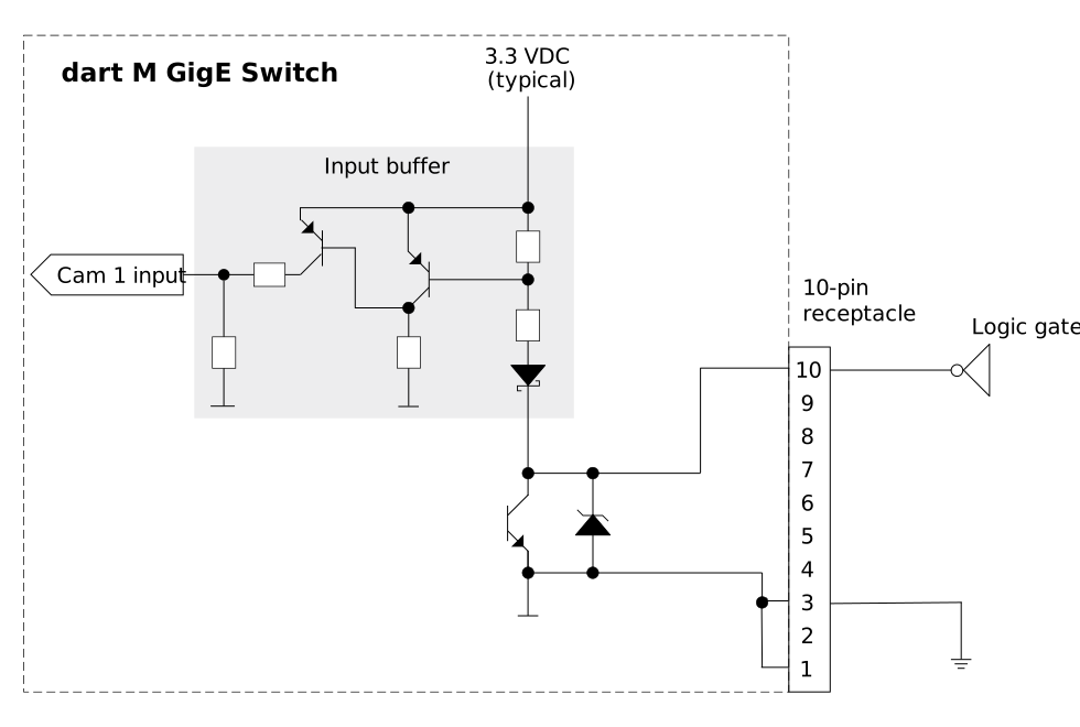
The following diagram shows a typical circuit with an input on a dart M GigE switch. As an example, GPI Cam1 is connected, and a TTL or CMOS logic gate is used in the external circuit.
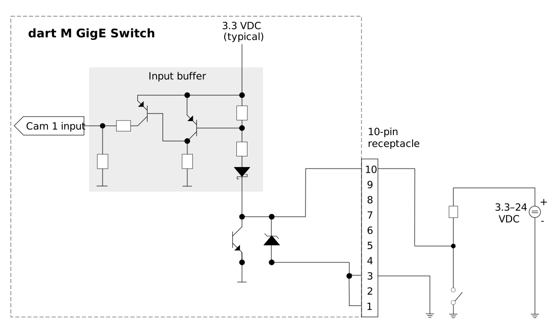
The following diagram shows a different example of an external circuit using an input of a dart M GigE switch.
Output Lines#
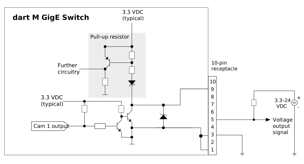
The following diagram shows a typical circuit using an output on a dart M GigE switch. As an example, GPO Cam 1 is connected. This circuit only works with devices that accept NPN communication.
Further Information#
- For information about the I/O connector pinout, see the corresponding dart M GigE switch topic:
- For information about how to configure the GPIO lines, see the General Purpose I/O (GPIO) Lines topic where you can get an overview about common tasks and the related feature topics.