Calibration vTool#
You can use the Calibration vTool as a preprocessing step followed by tools like the Geometric Pattern Matching vTool, the Region Feature Extraction vTool, or the Measurements vTools. If you have calibrated your camera, any subsequent tools will output pixel coordinates as well as world coordinates (in meters).
To buy a license for the Calibration vTool, visit the Basler website.
Calibration vTool Versions#
Two versions of the Calibration vTool are available. The following table shows the differences between the versions.
| Basic | Pro | |
|---|---|---|
| Can you choose between different distortion models? | No | Yes |
| Can you choose between different projection models? | No | Yes |
| Buy license | Visit Basler website | Visit Basler website |
How It Works#
Depending on the lens mounted on the camera, the raw image exhibits a certain amount of radial distortion. Also, without calibration, any measurements you take refer only to pixel coordinates in the image.
Using the Calibration vTool has the following benefits:
- The calibration process produces transformation data that is applied to raw images to remove distortion effects.
The result are images that look they were taken by an ideal and linear pinhole camera, i.e., where straight lines in the target scene are projected as straight lines onto the image. - Rectification eliminates perspective distortion.
Perspective distortion occurs if lenses with wider angles are used or if the camera is not pointing perpendicularly at the measurement plane where the objects to be inspected are placed.
As an example, if the viewing direction of the camera is oblique, a square in the world will be seen by the camera as a general quadrangle, where opposite sides aren't parallel but intersect at vanishing points.
Therefore, if the mechanical setup doesn't allow you to mount the camera perpendicularly to the inspection plane, camera calibration will ensure that the image is rectified and will look like a true representation of the object. - Calibration establishes a relation between image coordinates in pixels and world coordinates in meters.
This way, tasks like measuring a distance in the real world or determining a gripping position for a robot can be solved. - When using the Calibration Pro vTool, you can choose between different distortion and projection models. This makes the calibration even more precise or specific as it allows you to factor in your application type and the lenses you're using.
Calibration Process#
Step 1: Preparation#
Calibration Plate#
The Calibration vTool allows you to calibrate a camera with respect to a single measurement plane. This requires a calibration plate. Out of the box, the Calibration vTool offers circle grid calibration plate in different sizes. They are available in the Calibration plate drop-down list.
Choose the size of the calibration plate according to the field of view of your camera. If your target scene includes the complete field of view, the calibration plate should cover more or less the complete image area.
In most situations, it is preferable for the calibration plate to be a little bit bigger than the image area. For optimum calibration results, you should ensure that the whole image area is covered by the circle grid of the calibration plate. If your target scene includes only a portion of the complete field of view, a calibration plate that only covers that particular area is sufficient.
To create your calibration plate, print one of the templates provided and glue it onto a firm, flat, and even surface, e.g., thick cardboard or an aluminum plate. For general applications or evaluation purposes, the printing precision of standard printers or plotters is likely to be sufficient.
If the sizes offered don't meet your requirements, custom calibration plates are available on request. For this, contact Basler Support.
Distortion Models (Pro Version Only)#
By choosing a distortion model appropriate for your application, you can generate more precise transformation data for correcting distortion effects. There are two models to choose from:
- Division: This model is suitable for most applications, especially for robot or part localization applications. It uses only one coefficient for modeling distortion. Therefore, it is very robust and produces good results.
- Polynomial: This model achieves even more accurate calibration results. It should be used for measurement applications or in case of stronger lens distortions. Five coefficients are used for modeling distortion.
Projection Models (Pro Version Only)#
Choosing a projection model allows you to factor in the type of lens you're using. There are two models to choose from:
- Perspective: This model is recommended when using entocentric lenses.
- Parallel: This model is recommended when using telecentric lenses.
To perform step 1, go to Configuring the vTool.
Step 2: Camera Calibration#
In this step, you acquire an image of the calibration plate. You can grab a live image with the camera or load an image from disk. Live images are useful because they allow you to move the calibration plate on the fly to find the right position for your measurements. The upper surface of the calibration plate defines the measurement plane.
Info
Calibrating the camera enables measurements only in a single world plane. This world plane is defined by the calibration plate. If the setup of your application changes, you need to recalibrate the camera.
The objects you want to measure have to lie on or close to this plane. Therefore, the objects to be inspected have to be flat or low in height. Alternatively, you have to ensure that the calibration plate's upper surface is at the same height as the objects' surface.
If the camera is looking perpendicularly onto the measurement plane and the lens has a small opening angle, the error caused by objects lying outside of the measurement plane can be neglected. Only if the angle between the measurement plane and the camera's viewing direction is oblique, the measurement error regarding position or distance gets significant.
In that case, Basler recommends restricting the variation of height between the objects to a value between 1–5 % relative to the object distance.
Once an image has been acquired, the calibration process starts immediately and the results are displayed below the image area.
Coloring in the image area immediately shows whether the calibration was successful. Circles highlighted in green have been detected successfully whereas red circles haven't been detected. Also, the origin of the world coordinate system is shown.
Info
The position and orientation of the world coordinate system is encoded in the calibration plate pattern and its description. You can't change this. If you want to adapt the world coordinate system to the needs of your application, use the machine calibration step to do so.
To perform step 2, go to Configuring the vTool.
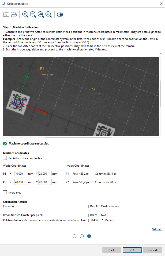
Step 3: Machine Calibration#
Machine calibration is an optional step in which you align the world coordinate system of the vision system with the coordinate system of the machine of which the vision system is a part of. Based on a common coordinate system, a robot, for example, can pick up an object at the position determined by the vision system.
If camera calibration is sufficient and you don't need aligned world coordinate systems for your application, you can end the calibration process here.
Considerations#
To define the machine coordinate system, two markers are used to define two points in the coordinate system, P1 and P2. For successful machine calibration, it is important to know the relation between the machine coordinate plane and the calibration plate plane. There are two options:
- Both planes are identical.
In this case, you can place the markers at any position of the calibration plate to define your own machine coordinate system. Knowing machine and image coordinates of the markers defines a transformation which allows you to transform image points measured into machine coordinates. -
The planes are parallel to each other.
Sometimes it's not possible or desired to have identical machine and calibration planes. Alternatively, the machine plane may be at a different height than the calibration plane. However, both planes must always be parallel to each other.Info
This setup is only recommended if the camera is pointing perpendicularly at the measurement plane. In practice, the viewing direction may deviate from the ideal configuration by a few degrees.
In cases where the viewing direction is oblique to the calibration plate, the machine plane must be at least close to the calibration plane. Otherwise, a systematic error occurs that is even greater for lenses with wider opening angles and more oblique viewing angles.
Methods#
There are three methods for supplying the markers that define the machine coordinate system.
Automatic with Aztec Codes#
Aztec codes are ideal for encoding information about coordinate positions as well as for providing a good visual marker for position detection in the image.
For this method, you generate and print two Aztec codes that encode positions in millimeters:
- One code encodes, e.g., the position of the coordinate system's origin: "0 0"
- The second code encodes a second point on the x axis of the coordinate system, e.g., 50 mm away from the first code: "50 0"
The notation for encoding positions is "point_coordinate_x point_coordinate_y".
The system will detect the position of the Aztec codes in the image and associate its world position with the decoded content of the codes.
Info
The center of the Aztec code defines the position of the marker in world coordinates.
The distance between the markers must be exactly the value defined by the encoded positions.
Manual with Aztec Codes#
In this method, the codes are generic and can contain any information you like, e.g., a short string. This makes the printing process easier because both codes can be identical. More importantly, this means that the codes can be placed at arbitrary positions. Just choose the positions that you want to register as machine coordinates.
For a robotics application, proceed like this: Place the codes and measure their positions with a suitable touch probe mounted on the robot hand. Then, acquire the image and enter the coordinates registered by the robot into the World Coordinates input fields.
Fully Manual#
This method gives you the flexibility to enter the coordinates of the two points in world and image coordinates. As in the method above, the world coordinates are known or registered from your system and entered into the World Coordinates input fields. You can adjust the image coordinates as required by dragging the P1 and P2 crosshairs in the image to the desired target positions.
There are two main scenarios where the fully manual method is useful:
- You can use any kind of marker that can be registered, e.g., the center of a circle, a corner point of a rectangular shape, or even a cross quickly sketched by hand on a piece of cardboard.
-
You can include the markers in your machine's design. That way, the positions of the markers are fixed and always known. Markers can be, e.g., small holes or suitable fiducial markers.
Info
If the machine has fixed markers, you have to place the calibration plate such that the distance to both markers is the same.
To perform step 3, go to Configuring the vTool.
Tips for Successful Calibration#
Consider the following aspects to ensure optimum calibration results (assuming 8-bit images with a gray value range of 0–255).
- Pattern coverage: At least one finder pattern must be visible to the camera. If two or more finder patterns are visible in the image, it's possible to detect whether the calibration plate is mirrored or not. Generally, the more of the calibration pattern is visible to the camera and the more of the field of view is filled by the calibration plate, the better.
- Circle diameter: The diameter of the of the circles in the grid should be at least 20 pixels in every image. This is essential for successful calibration.
- Contrast: The contrast between the light and dark areas in the images of the calibration plate should be at least 100 gray values.
- Overexposure: Avoid overexposed images. The light areas in the images of the calibration plate shouldn't exceed a gray value of 240, especially not in the neighborhood of the finder patterns.
- Homogeneity: Ensure homogeneous illumination and avoid reflections. As a rule of thumb, the difference in gray values between lightest white part and darkest white part in the images you take, shouldn't exceed 45.
Common Use Cases#
Geometric Pattern Matching#
If you use rectified images, your matching results will be more accurate. The reason is that a flat object will look the same independent of its position on the measurement plane because lens distortion or perspective distortion are eliminated.
Also, the transformation data produced by the calibration process enables the Geometric Pattern Matching vTool to output the world coordinates of the center of a pattern.
Region Feature Extraction#
The Region Feature Extraction vTool calculates features of a region, e.g., area or center of gravity, and allows you to extract them. Using a calibrated setup allows you to transform features, e.g., coordinates, lengths, or areas, into measurement units, e.g., meters or square meters.
Measurements#
The Measurements Basic vTool determines the positions of edges or distances between edges with high precision. If you use the Calibration vTool for preprocessing, you can prevent lens distortion and perspective distortion. Also, you will be able to get the results in metric measurement units (coordinates and distances).
Info
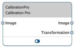
To fully benefit from the Calibration vTool ensure that both its output pins (Image and Transformation) are connected properly to all subsequent vTools.
The Measurements Pro vTools work in a similar manner but allow you to measure complete geometric shapes.
Configuring the vTool#
To configure the Calibration vTool:
-
In the Recipe Management pane in the vTool Settings area, click Open Settings or double-click the vTool.
The Calibration Basic/Pro dialog opens at step 1.
For more information, see Step 1: Preparation.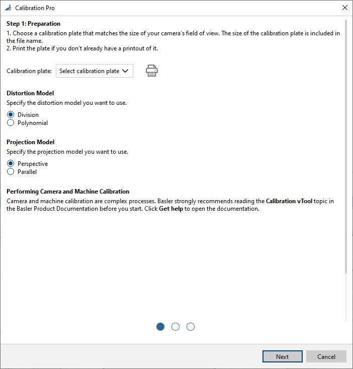
-
In the Calibration plate drop-down list, select the size of the plate you want to use.
-
If you haven't got an actual plate yet, click the Print button to print the desired plate.
-
Select a distortion model and a projection model (Pro version only).
-
Click Next.
Step 2 of the Calibration dialog opens.
For more information, see Step 2: Camera Calibration.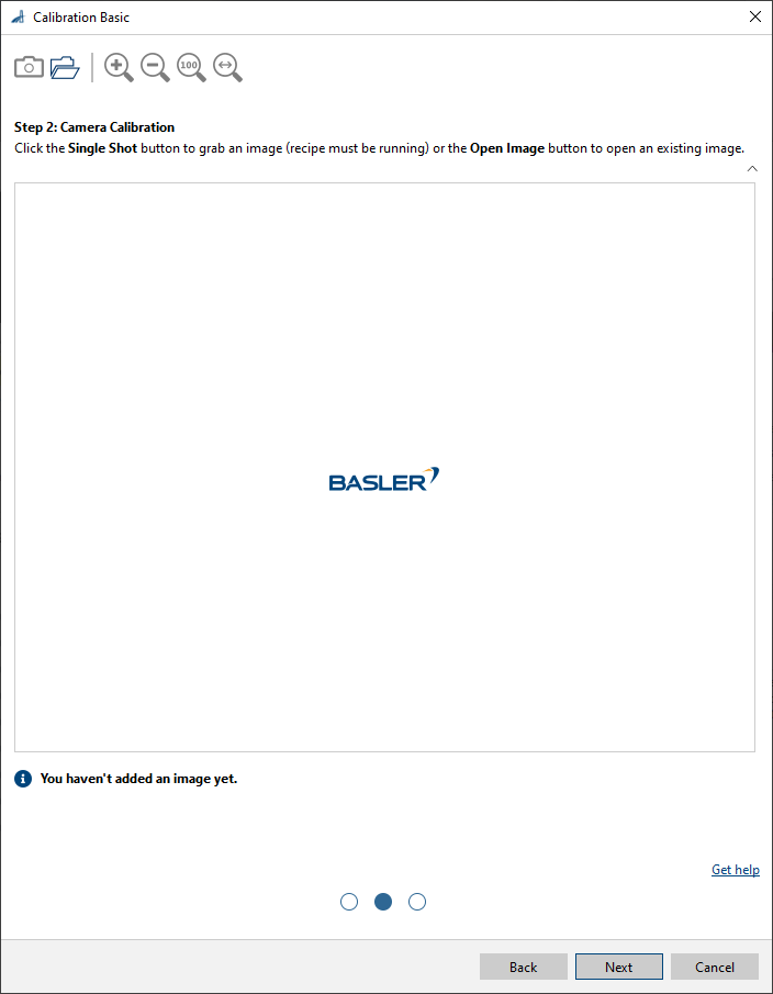
-
Place the calibration plate at the position of the image where you want to measure.
The upper surface of the calibration plate defines the measurement plane. -
Capture or open an image.
Either use the Single Shot button to grab a live image or click the Open Image button to open an existing image.
Once an image has been loaded, the calibration process starts immediately. When it's finished, the results are displayed below the image area. If the calibration process was successful, a green check mark appears below the image area.Info
The sizes of the images used for calibration must be identical to the sizes of the processed images.
-
Check the results table to see whether your requirements are met.
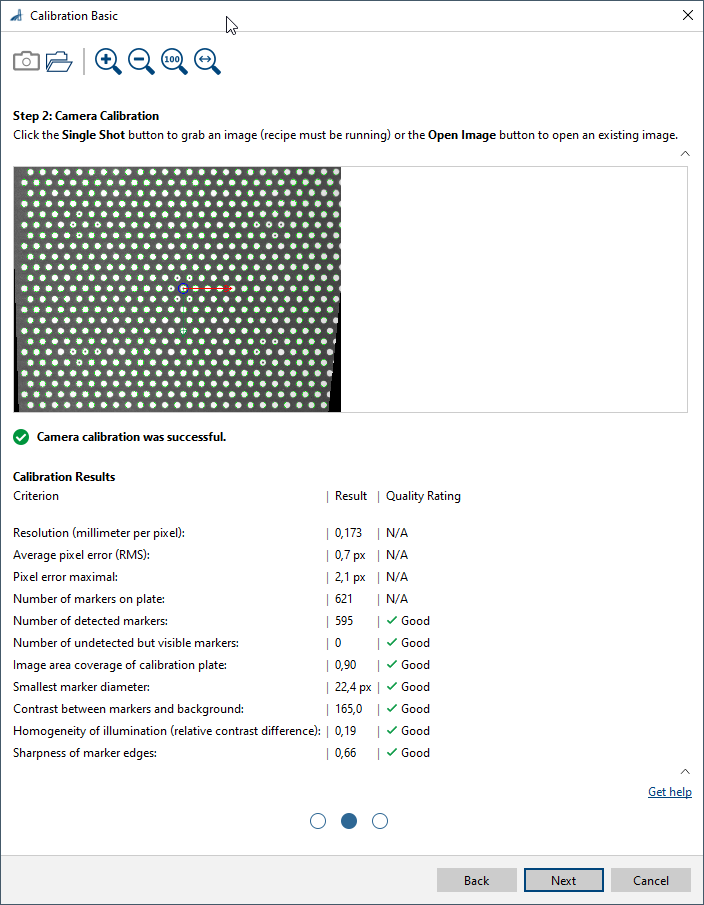
You can hide the table using the arrow button. If you do, the image area expands, making it easier to inspect the image details.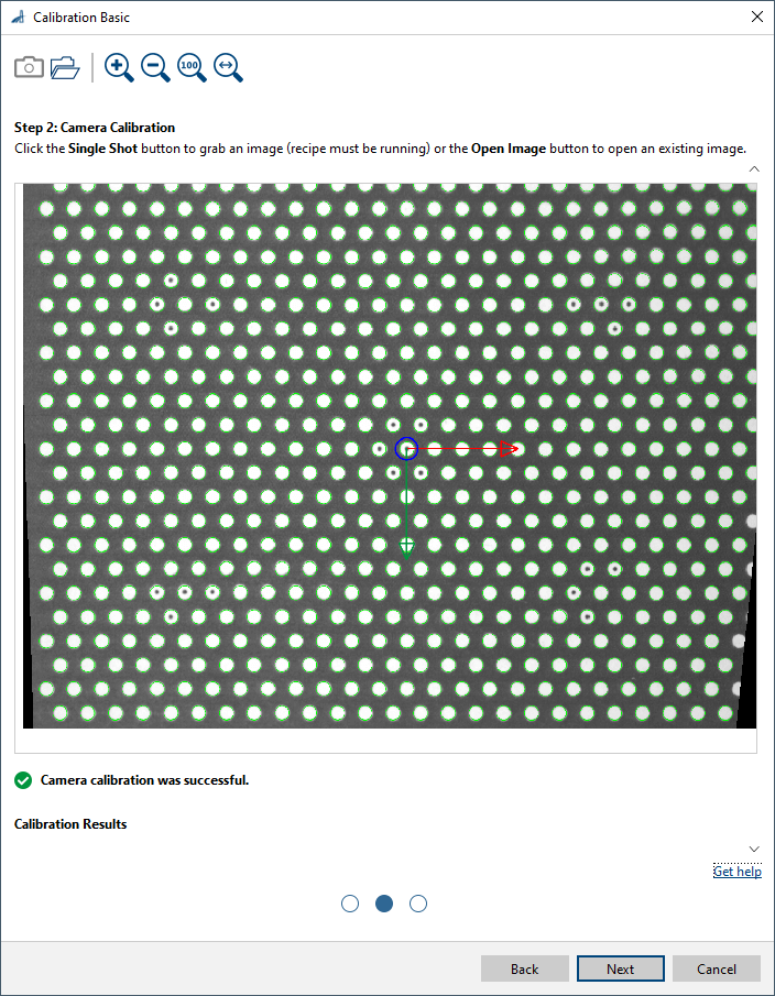
-
Click Next.
Step 3 of the Calibration dialog opens.
For more information, see Step 3: Machine Calibration. -
If you want to calibrate your machine, click the Enable Machine Calibration button at the right end of the toolbar.
If you want to finish with just the camera calibration, leave the settings dialog by clicking OK.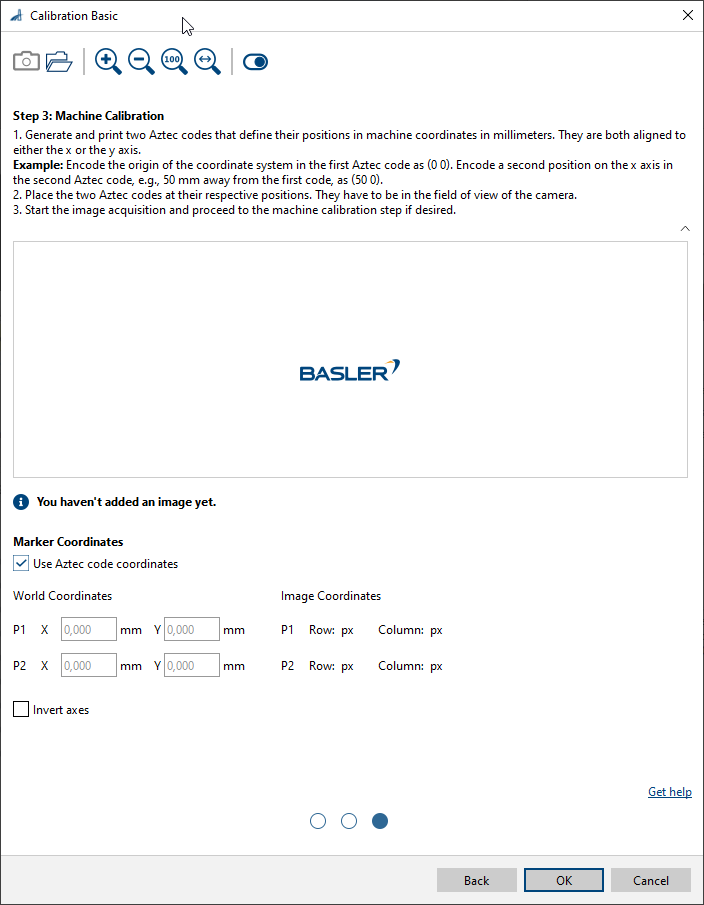
-
Decide which method you want to use to define the machine's coordinate system.
-
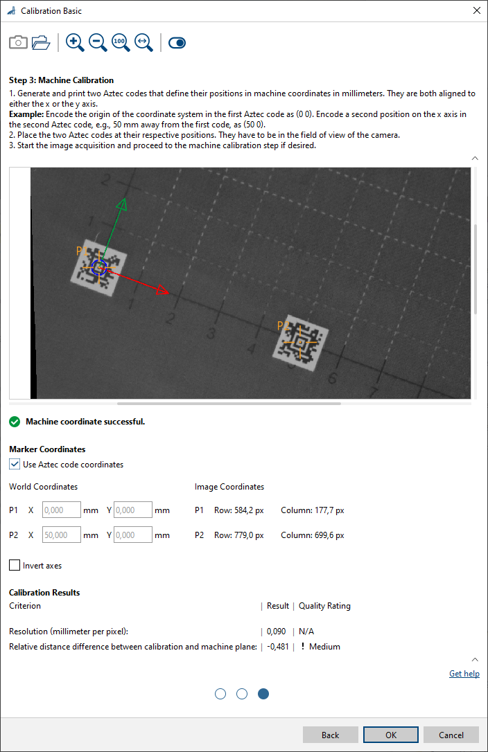
Automatic with Aztec Codes:
-
Generate two Aztec codes with two different positions in the coordinate system encoded in them (typically, the origin of the coordinate system and a second position).
-
Print the Aztec codes.
-
Place the two Aztec codes at the exact positions of the world or machine coordinate system.
-
Select the Use Aztec code coordinates check box.
-
Capture or open an image.
Either use the Single Shot button to grab a live image or click the Open Image button to open an existing image.
Once an image has been loaded, the calibration process starts immediately. When it's finished, the results are displayed below the image area. If the calibration process was successful, a green check mark appears below the image area. The Aztec codes are visualized by crosshairs in the image, and the origin of the world coordinate system is visualized as well. -
Check the results table to see whether your requirements are met.
-
If you want to define the orientation of the z axis in accordance with your machine's coordinate system, select the Invert axes check box.
-
-
Manual with Aztec Codes:
-
Generate two Aztec codes with a generic string encoded in them.
The strings can be identical, in which case you only need to generate one Aztec code and print two copies of it. -
Print the Aztec codes.
-
Place the Aztec codes at convenient positions in the image area.
-
Measure the positions of the Aztec codes in world coordinates.
-
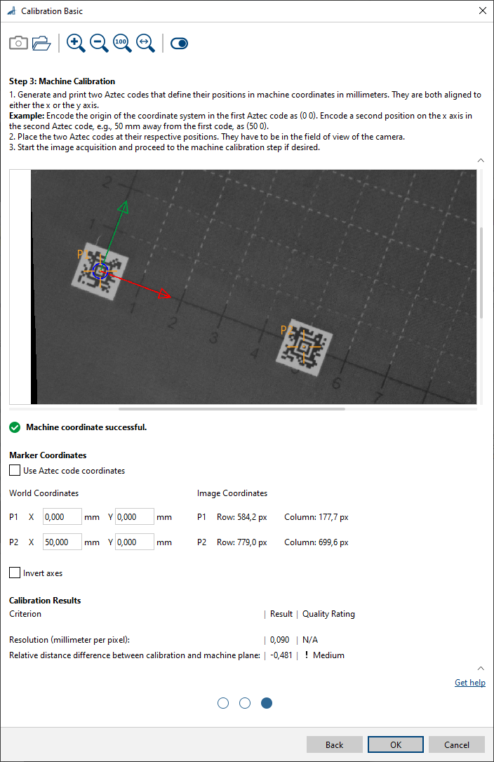
Clear the Use Aztec code coordinates check box.
-
Capture or open an image.
Either use the Single Shot button to grab a live image or click the Open Image button to open an existing image. -
Enter the coordinates for P1 and P2 in the respective World Coordinates input fields.
-
-
Fully manual:
-
Clear the Use Aztec code coordinates check box.
-
Enter the world coordinates for P1 and P2 in the respective input fields.
They are either known (because they are fixed by design), or you have to measure them. -
To specify the P1 and P2 image coordinates, drag the crosshairs in the image area to the desired positions.
-
-
You can view the result of the calibration in a pin data view. Here, you can select which outputs to display.
Inputs#
Image#
Accepts images directly from a Camera vTool or from a vTool that outputs images, e.g., the Image Format Converter vTool.
- Data type: Image
- Image format: 8-bit to 16-bit mono or color images (see Supported Pixel Formats)
Outputs#
Image#
Returns the rectified image. The output image can be used by any vTool accepting images as input.
- Data type: Image
- Image format: Color or mono images (see Supported Pixel Formats)
Transformation#
Returns the transformation data that transforms the pixel coordinates of the rectified image into world coordinates. The transformation data can be used by any tool accepting transformation data as input to determine the world coordinates for a set of pixel coordinates.
- Data type: Transformation Data
Supported Pixel Formats#
Depending on the pixel format of the input image, the Calibration vTool outputs the following pixel formats:
| Input Pixel Format | Output Pixel Format |
|---|---|
| Bayer GR 8 | RGB 8 Planar |
| Bayer GR 16 | RGB 16 Planar |
| Bayer RG 8 | RGB 8 Planar |
| BGRA 8 Packed | RGB 8 Planar |
| BGR 8 Packed | RGB 8 Planar |
| Mono 8 | Mono 8 |
| Mono 10 | Mono 10 |
| Mono 12 | Mono 12 |
| Mono 16 | Mono 16 |
| RGB 8 Packed | RGB 8 Planar |
| RGB 16 Packed | RGB 16 Planar |
| RGB 8 Planar | RGB 8 Planar |
| RGB 16 Planar | RGB 16 Planar |
Related vTools#
Typical Predecessors#
Typical Successors#
- Region Feature Extraction vTool
Allows you to determine region features in world coordinates. - Geometric Pattern Matching vTool
Connect the Geometric Pattern Matching Pro vTool to determine the center and orientation of objects in world coordinates. - Measurements Basic vTool
Allows you to determine positions and distances in world coordinates. - Circle Measurements Pro vTool
Allows you to determine positions and distances in world coordinates. - Ellipse Measurements Pro vTool
Allows you to determine positions and distances in world coordinates. - Line Measurements Pro vTool
Allows you to determine positions and distances in world coordinates. - Rectangle Measurements Pro vTool
Allows you to determine positions and distances in world coordinates.