Region Morphology vTool#
You can reduce or expand regions, remove small structures, remove holes, or fill holes. This ensures that subsequent processing is more efficient or delivers better results.
The Region Morphology vTool accepts regions or region arrays via the Regions input pin and outputs region arrays via the Regions output pin.
The Regions output of the Region Morphology vTool can also be used as Roi input for vTools with a Roi input pin. For more information, see the ROI Creator vTool topic.
The Region Morphology vTool is available in the Blob Analysis Basic and Color Blob Analysis Basic licenses. To buy a license, visit the Basler website.
How It Works#
The purpose of region morphology is the manipulation of regions. The basic morphology operations Erosion and Dilation are based on a region mask. The Fill operation doesn't require a mask.
Mask Shapes#
Circular and rectangular masks are available. Depending on the mask shape, you can specify width and height or radius. Every mask has a well-defined center. During the morphology operation, the mask is moved over the image line by line.
For rectangular masks with odd width and height values (e.g., 3, 5, 7, etc.), the center of the mask is the same as the center of gravity of the mask. The mask is symmetrical with respect to the center.
For circular masks with a radius of an integer plus 0.5 (e.g., 1.5, 2.5, 3.5, etc.), the center of the mask is the same as the center of gravity of the mask. The mask is symmetrical with respect to the center.
If you open the settings dialog for the first time and select a rectangular mask, width and height are linked. This means that you can change both parameters at the same time and the resulting mask will be square. You can also set width and height separately. To do this, click the chain icon to break the link between width and height.
- Options linked:
- Options unlinked:
Morphology Operations#
This is how the different operations work:
- Erosion: Wherever the mask fits completely inside the input region, the pixels hit by the center of the mask are added to the output region. This reduces the area of the region.
- Dilation: Wherever the mask and the input region share at least one pixel, the pixels hit by the center of the mask are added to the output region. This expands the area of the region.
- Opening: This is a concatenation of erosion and dilation. The mask for the dilation is the same mask as for the erosion but rotated by 180 °. This operation removes structures that are smaller than the mask from the region. The output region is more or less the same size and shape as before.
- Closing: This is a concatenation of dilation and erosion. The mask for the erosion is the same mask as for the dilation but rotated by 180 °. This operation fills or bridges gaps that are smaller than the mask in the region. The region is more or less the same size and shape as before.
- Fill: This fills holes within the region. This operation doesn't require a mask.
In addition to the options listed above, you can also perform region splitting. This turns connected components of a region into separate regions. If you select the corresponding check box, the connected components of all single or multiple input regions are computed.
A connected component is a region where all pixels have a direct neighboring pixel (in horizontal, vertical, and diagonal direction). Regions that are not connected will be split into individual output regions.
You can also perform region splitting on the raw input region without any morphology operation before.
Info
If you're using region morphology as part of a blob analysis, you can concatenate multiple Region Morphology vTools in order to compute the desired output region at the end.
Depending on the goal of the blob analysis, you may use the Region Selection vTool as an intermediate or final step in a series of region morphology operations to filter out just the relevant regions.
Examples#
The following sections illustrate the different morphology operations using sample images.
Erosion and Dilation#
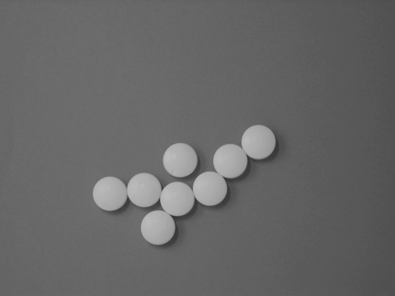
The following images show you how to use two morphology operations (Erosion and Dilation) consecutively to separate touching objects while retaining their original shapes. As a result, the number of objects can be counted properly, potentially followed by an inspection based on region features.
This is the input image showing white tablets:
This is the image with the initial regions found, e.g., after color classification:

After applying an Erosion operation, the regions look like this:
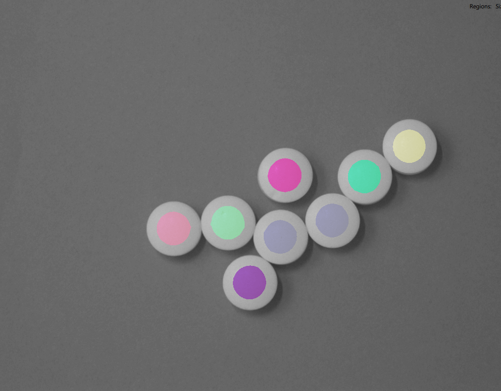
Finally, after applying a Dilation operation, the tablets are separated.

Opening and Fill#
The Opening operation is often used to suppress small regions, e.g., resulting from image noise or clutter, which results in an imperfectly segmented region. In other words, Opening can be used to filter out significantly large region structures by using an appropriate mask.
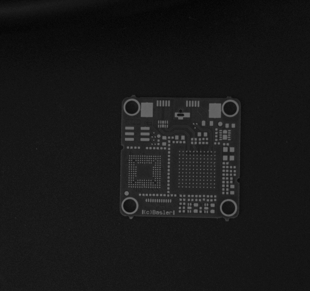
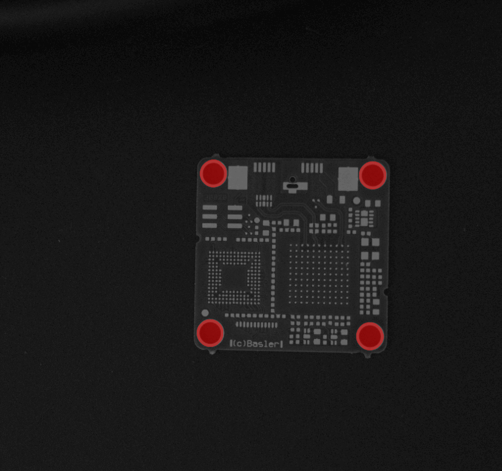
The following images show that by opening a region with a circular mask of approximately half the size of the target object the fiducials of a circuit board can be detected.
Region filling is used as an intermediate step to turn the rings into filled circles.
This is the input image showing a circuit board:
Using thresholding, the light structures in the image can be seen in the output regions:
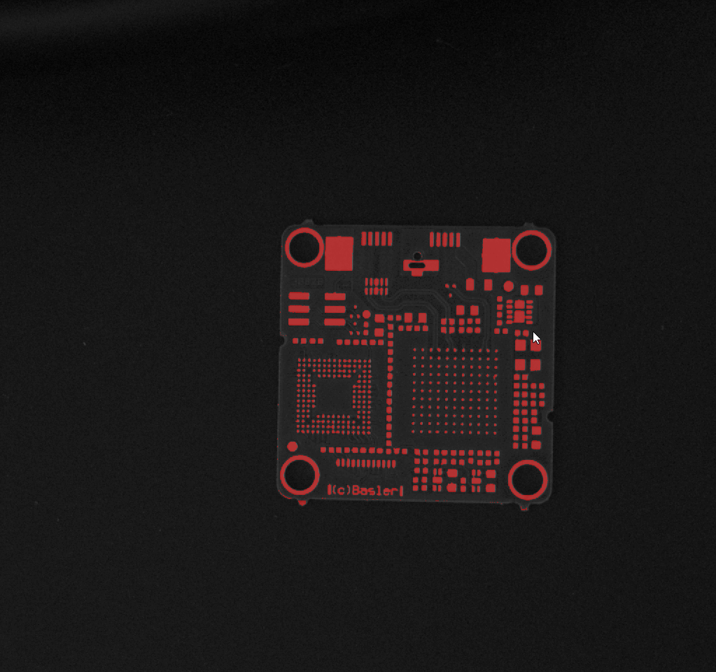
After applying the Filling, the rings are filled:
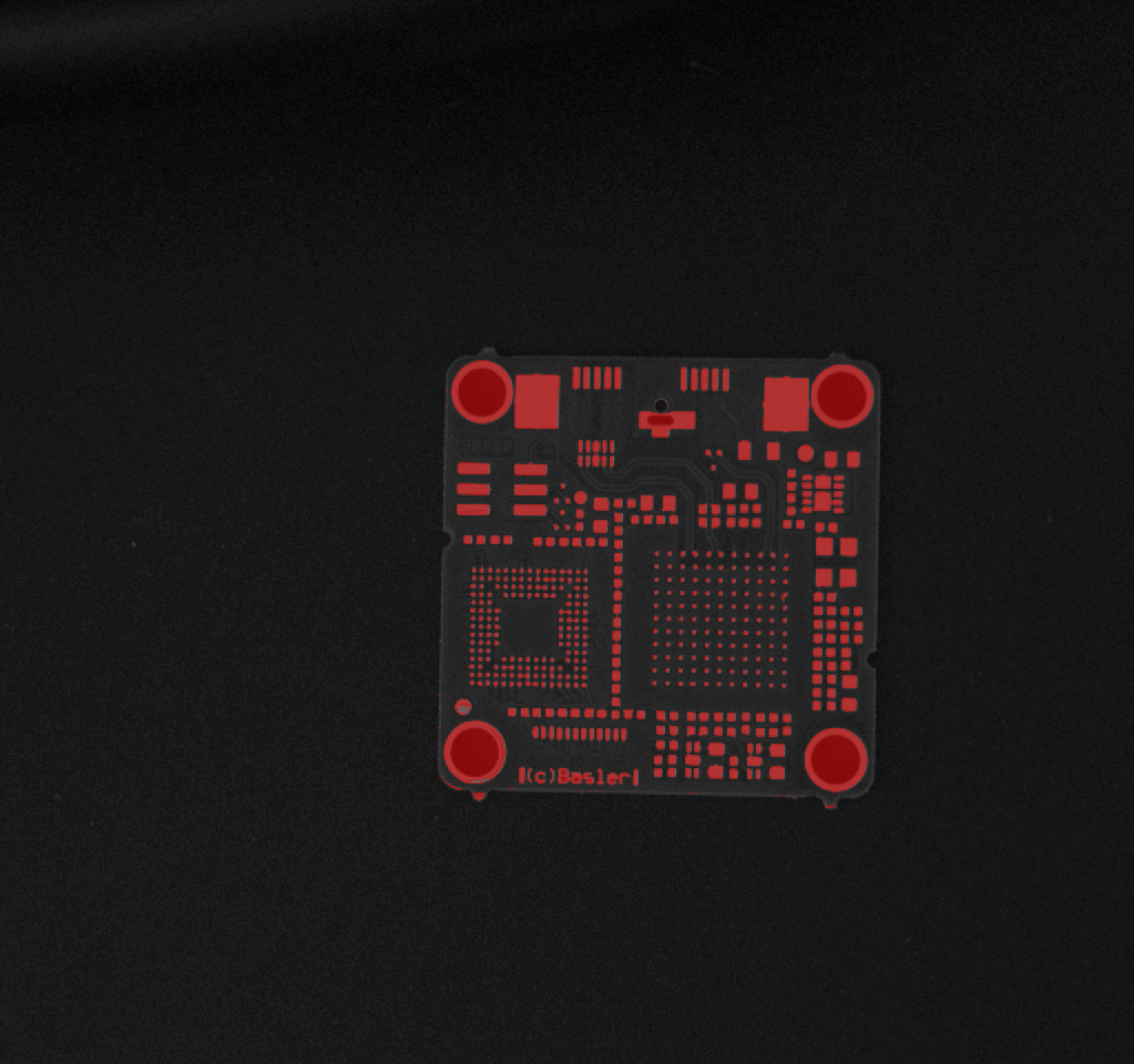
Finally, applying the Opening will eliminate all small regions and leaves only the fiducials as detected regions:
Closing#
The Closing operation is basically used to close indentations in regions, fill gaps, or join individual region segments.
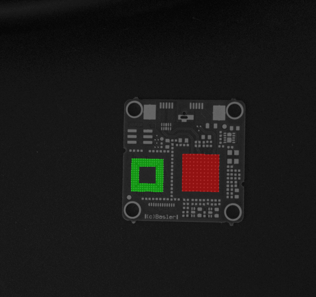
Based on the same circuit board example as before, this example shows how to segment the ball grid array regions. The starting point is the thresholded image showing the light structures shown above.
Apply a Closing operation with a rectangular mask big enough to bridge the gaps between all the balls of the ball grid array.
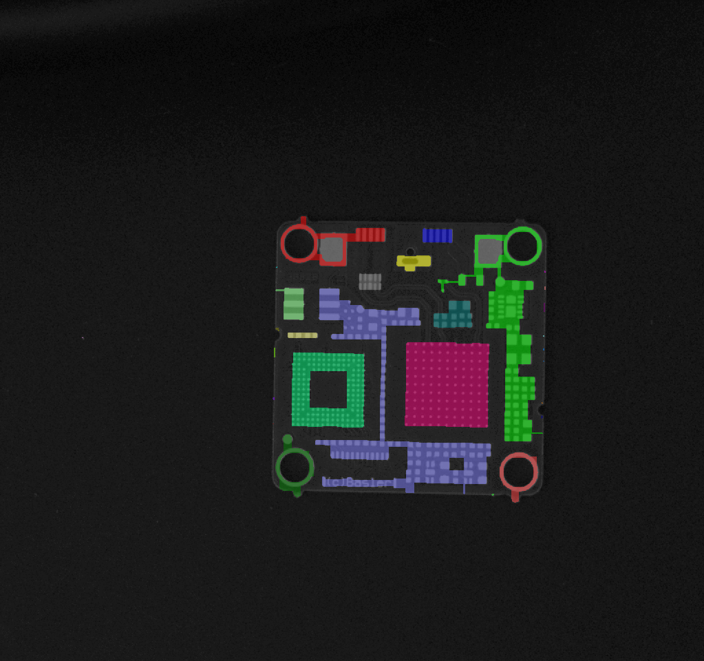
Apply an Opening operation to reduce small unwanted regions.
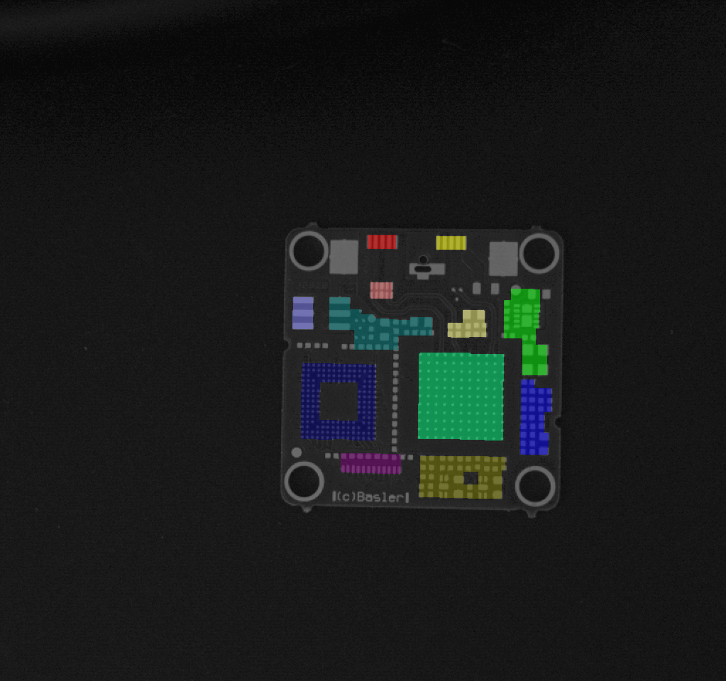
Finally, use the Region Selection vTool to select both ball grid array regions based to their size.
Common Use Cases#
- Shrinking regions by using circular or rectangular Erosion
- Expanding regions by using circular or rectangular Dilation
- Removing small objects by using Opening
- Filtering out bigger objects by using Opening with an appropriate mask shape
- Filling small holes or indentations by using Closing
- Bridging gaps between regions by using Closing
- Filling holes within regions by using Fill
- Splitting connected components of regions into separate regions in order to count the number of regions
Configuring the vTool#
To configure the Region Morphology vTool:
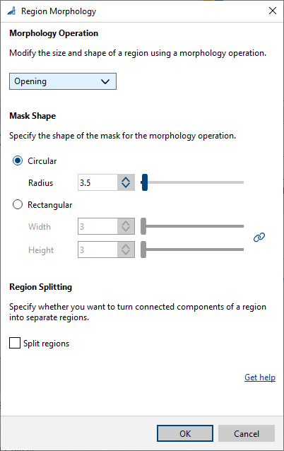
- In the Recipe Management pane in the vTool Settings area, click Open Settings or double-click the vTool.
The Region Morphology dialog opens. - In the Morphology Operation area, select the operation you want to carry out.
If you only want to split regions without performing any morphology operations, select Off. - In the Mask Shape area, select the shape and the size of the mask.
A mask is required for the Erosion, Dilation, Closing, and Opening operations. - In the Region Splitting area, specify whether you want to split the connected components of a region into separate regions.
Splitting can also be used directly on the input image without performing any morphology operations first.
You can view the result of the morphology operation in a pin data view. Here, you can select which outputs to display.
Inputs#
Regions#
Accepts a single or multiple regions.
- Data type: Region, Region Array
Outputs#
Regions#
Returns a single or multiple processed regions.
- Data type: Region Array
Related vTools#
Typical Predecessors#
- Color Classifier vTool
- Auto Thresholding vTool
- Absolute Thresholding vTool
- Relative Thresholding vTool