Image Combiner vTool#
Image combination is a preprocessing step to combine the information of two images using basic arithmetic operations like addition, subtraction, multiplication, and division.
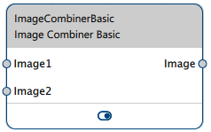
The Image Combiner vTool accepts two images via the Image1 and Image2 input pins and outputs the combined image via the Image output pin. Both input images must have the same pixel format.
The Image Combiner vTool is available in the Preprocessing Basic license. To buy a license, visit the Basler website.

Image Combiner vTool Versions#
Two versions of the Image Combiner vTool are available: Starter and Basic. Both versions' features are identical.
How It Works#
You can combine images from the same input source, e.g., one Camera vTool, or from two input sources, e.g., two Camera vTools. If you have two input sources, you have to synchronize these inputs using the Data Synchronizer vTool. Otherwise, errors may occur sporadically because the inputs aren't in synch and therefore can't be combined properly.
Combiner Operations#
The Image Combiner vTool offers the following combiner operations.
- Addition: Adds gray values pixel by pixel.
g1 + g2 = gout - Subtraction: Subtracts gray values of image 2 pixel by pixel from gray values of image 1.
g1 - g2 = gout - Multiplication: Multiplies gray values pixel by pixel.
g1 * g2 = gout - Division: Divides gray values of image 1 pixel by pixel by gray values of image 2.
g1 / g2 = gout - Absolute Difference: Performs a subtraction as described above and determines the absolute value. This operation can be used to compute the difference between two images.
Abs(g1 - g2) - Minimum: Compares gray values pixel by pixel between image 1 and image 2 and assigns the lower value of the two to the corresponding pixel in the output image.
Min(g1,g2) - Maximum: Compares gray values pixel by pixel between image 1 and image 2 and assigns the higher value of the two to the corresponding pixel in the output image.
Max(g1,g2)
Info
For all combiner operations, the size and pixel format of both images must be identical.
Arithmetic Operations#
Addition, subtraction, multiplication, and division are binary operations. These operations change the gray value range of the resulting image. As a result, gray value under- or overflows may occur. If this happens, gray values that are out of range are automatically set to the highest or lowest gray value of the input image format.
Example: In an 8-bit image, negative output gray values are set to zero and output gray values above 255 are set to 255.
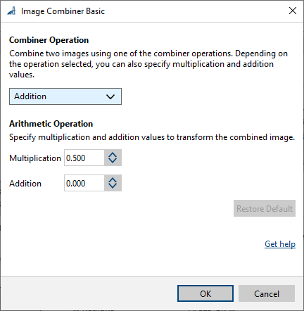
To avoid this, the Image Combiner offers secondary arithmetic operations (multiplication and addition) with which you can improve the intermediate result of the main operation. This is illustrated by the following formula:
gout = operation (g1, g2) * multiplication factor + addition value
These additional multiplication or addition steps are often used for unsigned image formats like 8-bit images to preserve the gray value range of the input image.
Example: To avoid a gray value overflow after combining two 8-bit input images by addition, specify a multiplication factor of 0.5 and an addition value of 0.0. After image subtraction, a multiplication factor of 0.5 and an addition value of 128 produces good results.
Common Use Cases#
Object Detection#
A simple approach to object detection is to take a reference image of the target scene without any objects present. This is the reference image or background image. To detect objects, you subtract the reference image from the inspection image to see where regions of pixels differ in terms of their gray values.
Afterwards, you can apply thresholding on the resulting difference image to segment regions where the deviation of gray values is significant. A typical workflow would be to start with the Image Smoothing vTool or Image Morphology vTool followed by the Image Combiner and a thresholding vTool.
Compared to the Relative Thresholding vTool, with which you can achieve similar results, using this combination of vTools offers you more choice in terms of filter types and mask shapes. The Image Morphology vTool for example offers rectangular and circular masks as well median and rank filtering whereas the Relative Thresholding vTool only includes rectangular masks and mean filtering.
Comparison of Two Inspection Images#
You can determine whether there are any differences between two images that were taken under the same conditions (e.g., same camera, illumination, camera perspective, and object) at different times. To do this, use the Subtraction or Absolute Difference operations.
Generation of a Virtual Image#
For development or testing purposes, certain kinds of combined images may be required. For example, you can add a specific noise pattern or background or multiply an image with a mask image.
Compensation of Non-homogeneous Illumination#
Non-homogeneous illumination or vignetting effects may cause different parts of the image to have different brightness values. This creates problems if, for example, you want to use a thresholding step afterwards that uses a single global threshold for the entire image.
To solve this problem, you could capture the underlying brightness distribution of the image by using mean or median filtering with a big mask. Once you have this brightness distribution image (preferably done during an offline calibration step), you can subtract it from the incoming inspection image or divide the incoming inspection image by it.
Configuring the vTool#
To configure the Image Combiner vTool:

- In the Recipe Management pane in the vTool Settings area, click Open Settings or double-click the vTool.
The Image Combiner Starter/Basic dialog opens. - In the Combiner Operations area, select the desired operation.
- If available, specify the desired Multiplication and Addition values for the secondary arithmetic operations.
You can view the result of the image combination in a pin data view.
Inputs#
Image1#
Accepts images directly from a Camera vTool or from a vTool that outputs images, e.g., the Image Format Converter vTool.
- Data type: Image
- Image format: 8-bit to 16-bit mono or color images (see Supported Pixel Formats). The pixel formats of Image1 and Image2 must be the same.
Image2#
Accepts images directly from a Camera vTool or from a vTool that outputs images, e.g., the Image Format Converter vTool.
- Data type: Image
- Image format: 8-bit to 16-bit mono or color images (see Supported Pixel Formats). The pixel formats of Image1 and Image2 must be the same.
Outputs#
Image#
Returns the combined image. The output image can be used by any vTool accepting images as input.
- Data type: Image
- Image format: Color or mono images (see Supported Pixel Formats)
Supported Pixel Formats#
Depending on the pixel format of the input image, the Image Combiner vTool outputs the following pixel formats:
| Input Pixel Format | Output Pixel Format |
|---|---|
| Bayer GR 8 | RGB 8 Planar |
| Bayer GR 16 | RGB 16 Planar |
| Bayer RG 8 | RGB 8 Planar |
| BGRA 8 Packed | RGB 8 Planar |
| BGR 8 Packed | RGB 8 Planar |
| Mono 8 | Mono 8 |
| Mono 10 | Mono 10 |
| Mono 12 | Mono 12 |
| Mono 16 | Mono 16 |
| RGB 8 Packed | RGB 8 Planar |
| RGB 16 Packed | RGB 16 Planar |
| RGB 8 Planar | RGB 8 Planar |
| RGB 16 Planar | RGB 16 Planar |
Related vTools#
Typical Predecessors#
- Camera vTool
- Calibration vTool
- Image Format Converter vTool
- Image Morphology vTool
- Image Smoothing vTool